
Related Manuals for Lenovo ThinkAgile MX


Summary of Contents for Lenovo ThinkAgile MX
- Page 1 ThinkAgile MX Certified Node Small Factor ThinkAgile MX1021 User Guide Machine Type: 7D1B, 7D2U...
- Page 2 Before using this information and the product it supports, be sure to read and understand the safety information and the safety instructions, which are available at: http://thinksystem.lenovofiles.com/help/topic/safety_documentation/pdf_files.html?cp=9_0 In addition, be sure that you are familiar with the terms and conditions of the Lenovo warranty for your server, which can be found at: https://datacentersupport.lenovo.com/us/zh/warrantylookup First Edition (May 2020) ©...
-
Page 3: Table Of Contents
Certified Nodes overview ..1 Remove the PCIe adapter ..ThinkAgile MX certified configurations ..1 Install the PCIe riser assembly .. - Page 4 Trademarks ....106 Important notes ....106 ThinkAgile MX Certified Node Small FactorThinkAgile MX1021User Guide...
-
Page 5: Safety
Vor der Installation dieses Produkts die Sicherheitshinweise lesen. Prima di installare questo prodotto, leggere le Informazioni sulla Sicurezza. Les sikkerhetsinformasjonen (Safety Information) før du installerer dette produktet. Antes de instalar este produto, leia as Informações sobre Segurança. © Copyright Lenovo 2020... -
Page 6: Safety Inspection Checklist
This equipment must be installed by trained service personnel, as defined by the NEC and IEC 60950-1, Second Edition, the standard for Safety of Information Technology Equipment. Lenovo assumes you are qualified in the servicing of equipment and trained in recognizing hazards in products with hazardous energy levels. - Page 7 Click the Power tab to see all line cords. • Make sure that the insulation is not frayed or worn. 3. Check for any obvious non-Lenovo alterations. Use good judgment as to the safety of any non-Lenovo alterations. 4. Check inside the solution for any obvious unsafe conditions, such as metal filings, contamination, water or other liquid, or signs of fire or smoke damage.
- Page 8 ThinkAgile MX Certified Node Small FactorThinkAgile MX1021User Guide...
-
Page 9: Chapter 1. Lenovo Thinkagile Mx Certified Nodes Overview
ThinkAgile MX Certified Nodes are a series of Microsoft Windows Server Software-Defined Datacenter (WSSD) Premium hyper-converged infrastructure (HCI)-certified node. ThinkAgile MX Certified Nodes are a series of Lenovo servers that require Microsoft Windows Server Software-Defined Datacenter (WSSD) certification for all connected components, not a solution bundled with a rack, PDUs, switches, or network cables. - Page 10 VMkernel Adapter vSwitch 0 vSwitch 1 VLAN Name VLAN ID VLAN Portgroup Assigned vSwitch VMKernel vMotion Provision- Manage- vSphere vSphere Adapter Logging ment Replica- Replica- Services tion tion NFC Adapter 1 Adapter 2 ThinkAgile MX Certified Node Small FactorThinkAgile MX1021User Guide...
-
Page 11: Chapter 2. Specifications
– PC4-21300 (single-rank, dual-rank), 2666 MT/s, error correcting code (ECC), double-data-rate 4 (DDR4) registered DIMM (RDIMM) – PC4-21300 (quad-rank), 2666 MT/s, error correcting code (ECC), double-data- rate 4 (DDR4) load reduced DIMM (LRDIMM) Note: For a list of supported processors, see http://www.lenovo.com/us/en/ serverproven/ © Copyright Lenovo 2020... - Page 12 • Mixing SATA drives and NVMe drives in the same M.2 SATA/NVMe 4-bay data adapter is not supported. PCIe riser assembly PCIe and M.2 riser assembly: • Slot 6: PCI Express 3.0 x16, (supports <75W, low profile, half-height, half-length PCIe adapter) ThinkAgile MX Certified Node Small FactorThinkAgile MX1021User Guide...
- Page 13 Table 1. Server Specifications (continued) Specification Description Integrated functions • Lenovo XClarity Controller, which provides service processor control and monitoring functions, video controller, and remote keyboard, video, mouse, and remote drive capabilities. • Front operator panel • LOM module connector (front of server): –...
- Page 14 EU ErP (EcoDesign) Directive (2009/125/EC) Implementing Measure (COMMISSION REGULATION (EU) 2019/1782 of 1 October 2019) requires manufacturers to provide the energy efficiency and rating information. Lenovo products are designed to work with a range of compatible chargers and different chargers may be shipped in box or purchased subsequently.
- Page 15 Table 1. Server Specifications (continued) Specification Description Acoustical noise emissions • Operation: (base configuration) – Minimum: 5.3 bels – Typical: 5.4 bels – Maximum: 5.7 bels • Idle – Minimum: 4.9 bels – Typical: 5.0 bels – Maximum: 5.4 bels Notes: 1.
- Page 16 Primary Protectors is not sufficient protection in order to connect these interfaces metallically to an OSP wiring system. Environment The ThinkAgile MX Certified Nodes complies with ASHRAE class A4 specifications. System performance may be impacted when operating temperature is outside ASHRAE A4 Specification or fan failed condition outside A2 Specification.
- Page 17 Table 1. Server Specifications (continued) Specification Description • Relative Humidity (non-condensing): – Operating: 8% to 90%, maximum dew point : 24°C (75.2°F) – Shipment/storage: 8% to 90%, maximum dew point : 27°C (80.6°F) • Non-operating (unpacked) storage can pass the following condition: 5% to 95% at 38.7°C (101.7°F) maximum dry-bulb temperature for 48 hrs.
-
Page 18: Shock And Vibration Specifications
500 Hz, 15 half-sine, ±X, √ (with heatsink) (with heatsink) min/axis ±Y, ±Z Four M.2 NVIDIA T4 0.21Grms, 15G, 3ms, NVMe drives 5-500 Hz, 15 half-sine, ±X, √ (with heatsink) min/axis ±Y, ±Z ThinkAgile MX Certified Node Small FactorThinkAgile MX1021User Guide... -
Page 19: Chapter 3. Server Components
This section provides information to help you locate the following: • Machine type and model information: When you contact Lenovo for help, the machine type, model, and serial number information helps support technicians to identify your server and provide faster service. The model number and serial number are on the ID label. -
Page 20: Front View
Figure 3. SE350 QR code Front view The front view of the server varies by the model. Front view of the server • 10G SFP LOM Package Figure 4. 10G SFP LOM Package front view ThinkAgile MX Certified Node Small FactorThinkAgile MX1021User Guide... -
Page 21: Front Operator Panel
Table 3. Components on the 10G SFP LOM Package front view Front operator panel Shared XClarity Controller (XCC) network connectors Attention: Only one network IP can be used. 2x RJ45 ports to support daisy-chain connection. The dual-port provide the ability to daisy-chain the Ethernet management connections thereby reducing the number of ports in the management switches and reducing the overall cable density needed for systems management. -
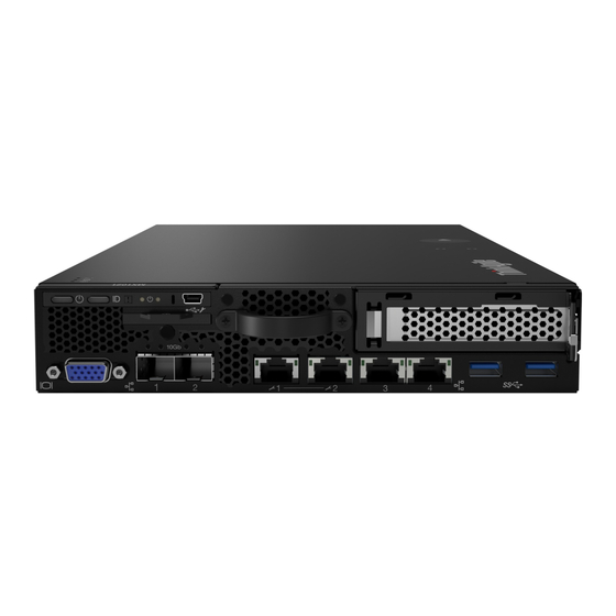
Page 22: Rear View
On: The server is turned on. Identification button/LED (blue): Use this blue LED to visually locate the server among other servers. This LED is also used as a presence detection button. You can use Lenovo XClarity Administrator to light this LED remotely. - Page 23 Table 6. Rear view - 12V power adapter model Not available USB 2.0 connectors RS-232 port (RJ-45) Power connector 1 Not available Power connector 2 Figure 8. Rear view - -48V power distribution module (PDM) Table 7. Rear view - -48V power adapter model Not available USB 2.0 connectors Power connector...
-
Page 24: System-Board Switches, Jumpers, And Buttons
Battery error LED XClarity Controller heartbeat LED Field-Programmable Gate Array (FPGA) Heartbeat LED ME Heartbeat LED Field-Programmable Gate Array (FPGA) error LED System-board connectors The following illustrations show the connectors on the system board. ThinkAgile MX Certified Node Small FactorThinkAgile MX1021User Guide... -
Page 25: Lom Packages
Figure 11. System-board connectors Table 10. System-board connectors Front operator panel connector Lock switch connector Intrusion switch connector 3V Battery (CR2032) Fan 1 connector Riser connector Fan 2 connector SATA Cable connector Fan 3 connector TPM connector M.2 boot adapter connector LOM module connector Power distribution module connector LOM packages... -
Page 26: System-Board Switches And Jumpers
The following illustrations show the location of the switches and jumpers on the server. Note: If there is a clear protective sticker on the top of the switch blocks, you must remove and discard it to access the switches. ThinkAgile MX Certified Node Small FactorThinkAgile MX1021User Guide... - Page 27 Figure 14. System-board switches The following table describes the switches on the system board. Table 11. System-board jumpers Usage description Switches block Switch number Switch name Machine Engine ME update mode Normal (default) (ME) firmware security override Accessed by technician Normal (default) only Password...
-
Page 28: Pcie Riser Assembly
Figure 15. PCIe and M.2 riser assembly Table 13. PCIe and M.2 riser assembly Slot 6: PCIe 3.0 x16, (supports <75W, low profile, half- Drives (Slot) 2-5, M.2 data adapters height, half-length PCIe adapter) ThinkAgile MX Certified Node Small FactorThinkAgile MX1021User Guide... -
Page 29: M.2 Drive And Slot Numbering
M.2 riser assembly Figure 16. M.2 riser assembly Table 14. M.2 riser assembly Drives (Slot) 6-9, M.2 data adapters Drives (Slot) 2-5, M.2 data adapters M.2 drive and slot numbering Use this information to locate the M.2 drive and slot numbering M.2 boot adapter Figure 17. -
Page 30: Parts List
Use the parts list to identify each of the components that are available for your server. For more information about ordering the parts shown in the Figure 19 “Server components ” on page 24: ThinkAgile MX Certified Node Small FactorThinkAgile MX1021User Guide... - Page 31 Tier 1 CRU at your request with no service agreement, you will be charged for the installation. • Tier 2 customer replaceable unit: You may install a Tier 2 CRU yourself or request Lenovo to install it, at no additional charge, under the type of warranty service that is designated for your server.
- Page 32 Server components Figure 19. Server components ThinkAgile MX Certified Node Small FactorThinkAgile MX1021User Guide...
- Page 33 Table 17. Parts listing Index Description Tier 1 CRU Tier 2 CRU Consuma- ble and Structural part Top cover √ Air baffle √ √ Intrusion switch cable √ Screwdriver in Misc kit √ Intrusion switch √ Processor heat sink √ Power adapter √...
- Page 34 ThinkAgile MX Certified Node Small FactorThinkAgile MX1021User Guide...
-
Page 35: Chapter 4. Hardware Removal, Installation And Management Guidelines
• Blue on a component indicates touch points, where you can grip to remove a component from or install it in the server, open or close a latch, and so on. © Copyright Lenovo 2020... -
Page 36: System Reliability Guidelines
• Prevent your necktie, scarf, badge rope, or long hair from dangling into the server. • Remove jewelry, such as bracelets, necklaces, rings, cuff links, and wrist watches. ThinkAgile MX Certified Node Small FactorThinkAgile MX1021User Guide... -
Page 37: Handling Static-Sensitive Devices
• Remove items from your shirt pocket, such as pens and pencils, in case they fall into the server as you lean over it. • Avoid dropping any metallic objects, such as paper clips, hairpins, and screws, into the server. Handling static-sensitive devices Review these guidelines before you handle static-sensitive devices to reduce the possibility of damage from electrostatic discharge. -
Page 38: Set The Network Connection For The Lenovo Xclarity
• If no monitor is attached to the server, you can set the network connection through the Lenovo XClarity Controller interface. Connect an Ethernet cable from your laptop to Lenovo XClarity Controller connector, which is at the rear of the server. For the location of the Lenovo XClarity Controller connector, see the rear view of the node. -
Page 39: Internal Cable Routing
• If you choose a DHCP connection, make sure that the MAC address for the server has been configured in the DHCP server. Step 4. Click OK to continue starting the server. Internal cable routing Some of the components in the server have internal cables and cable connectors. To connect cables, observe the following guidelines: •... -
Page 40: Turn Off The Server
Turn off the server The server remains in a standby state when it is connected to a power source, allowing the Lenovo XClarity Controller to respond to remote power-on requests. To remove all power from the server (power status LED off), you must disconnect all power cables. -
Page 41: Management Options
• Use the Lenovo XClarity Provisioning Manager to configure the RAID if you have installed or removed the M.2 backplane and M.2 drive. Management options Multiple management interfaces are available for managing your ThinkAgile MX Certified Nodes servers. Lenovo XClarity Administrator Lenovo XClarity Administrator is a centralized, resource-management solution that simplifies infrastructure management, speeds responses, and enhances the availability of Lenovo server systems and solutions. -
Page 42: Updating Firmware
You can use the tools listed here to update the firmware listed on the ThinkAgile MX Certified Nodes Best Recipe site for your server and the devices that are installed in the server as. All code levels must be contained within the same Best Recipe Release. -
Page 43: Memory Configuration
Additional information about using Lenovo XClarity Provisioning Manager to update firmware is available http://sysmgt.lenovofiles.com/help/index.jsp?topic=%2FLXPM%2Fplatform_update.html • Lenovo XClarity Controller If you need to install a specific update, you can use the Lenovo XClarity Controller interface for a specific server. Notes: – To perform an in-band update through Windows or Linux, the operating system driver must be installed and the Ethernet-over-USB (sometimes called LAN over USB) interface must be enabled. -
Page 44: Dc Persistent Memory Module (Dcpmm)
• All the DCPMMs that are installed must be of the same Lenovo part number. • All DRAM memory modules that are installed must be of the same type, rank, and capacity with minimum capacity of 16 GB. It is recommended to use Lenovo DRAM memory modules of the same part number. - Page 45 For more details, see https://sysmgt.lenovofiles.com/help/topic/LXPM/using_LXPM.html Note: If the text-based interface of Setup Utility opens instead of Lenovo XClarity Provisioning Manager, go to System Settings ➙ <F1> Start Control and select Tool Suite. Then, reboot the system and press F1 as soon as the logo screen appears to open Lenovo XClarity Provisioning Manager.
- Page 46 • Lenovo XClarity Essentials OneCLI Some management options are available in commands that are executed in the path of Lenovo XClarity Essentials OneCLI in the operating system. See https://sysmgt.lenovofiles.com/help/topic/toolsctr_cli_ to learn how to download and use Lenovo XClarity Essentials lenovo/onecli_t_download_use_tcscli.html OneCLI.
- Page 47 These values are selectable options for DCPMM settings, and do not represent the current DCPMM status. In addition, you can take advantage of a memory configurator, which is available at the following site: http://1config.lenovo.com/#/memory_configuration Alternatively, set DCPMM Goals with the following commands in OneCLI: 1. Set create goal status.
- Page 48 In the case the passphrases are lost or forgotten, the stored data cannot be backed up or restored, but you can contact Lenovo service for administrative secure erase. • After three failed unlocking attempts, the corresponding DCPMMs enter “exceeded” state with a system warning message, and the DCPMM unit can only be unlocked after the system is rebooted.
-
Page 49: Adding Memory Modules With Dcpmms
• All the DRAM DIMMs that are installed must be of the same type, rank, and capacity with minimum capacity of 16 GB. It is recommended to use Lenovo DRAM DIMMs of the same part number. 3. See “Memory module installation rules” in ThinkSystem SR630 Maintenance Manual to determine the new configuration, and acquire memory modules accordingly. - Page 50 10. Configure DCPMMs so that the capacity is available for use (see “Configuring DC Persistent Memory Module (DCPMM)” on page 36). 11. Restore the data that have been backed up. ThinkAgile MX Certified Node Small FactorThinkAgile MX1021User Guide...
-
Page 51: Chapter 5. Hardware Replacement Procedures
To remove a M.2 data adapter, complete the following steps: Watch the procedure. A video of the process is available: • Youtube: https://www.youtube.com/playlist?list=PLYV5R7hVcs-A25P7vBoGa_wn7D7XTgDS_ • Youku: http://list.youku.com/albumlist/show/id_50483444 Step 1. Remove the screws on the both side to remove the bezels from the riser assembly. © Copyright Lenovo 2020... - Page 52 Grasp the M.2 data adapter by its edges and carefully pull it out of the slot. • M.2 riser assembly Figure 21. M.2 data adapter removal • PCIe and M.2 riser assembly ThinkAgile MX Certified Node Small FactorThinkAgile MX1021User Guide...
-
Page 53: Install A M.2 Data Adapter
Figure 22. M.2 data adapter removal If you are instructed to return the defective component, please package the part to prevent any shipping damage. Reuse the packaging the new part arrived in and follow all packaging instructions. Install a M.2 data adapter Use this information to install a M.2 data adapter. - Page 54 Insert the bezels to the riser assembly on the both sides and install the six screws as shown. Note: The color and the size of the screws on each side are different, make sure to install the short ones one the left and long ones on the right. ThinkAgile MX Certified Node Small FactorThinkAgile MX1021User Guide...
-
Page 55: Remove The M.2 Boot Adapter
Figure 25. M.2 data adapter installation After you install a M.2 data adapter, complete the following steps: 1. Install the PCIe riser assembly (see “Install the PCIe riser assembly” on page 50 for instructions). 2. Install the node if needed (see “Install a compute node” on page 58). 3. -
Page 56: Install The M.2 Boot Adapter
For more information about the M.2 adapter, see https://lenovopress.com/lp0769-thinksystem-m2-drives- adapters Step 1. Align the M.2 boot adapter with the connector on the system board, and press the adapter straight into the connector. ThinkAgile MX Certified Node Small FactorThinkAgile MX1021User Guide... -
Page 57: Remove The Pcie Adapter
Figure 27. M.2 boot adapter installation After you install the M.2 boot adapter, complete the following steps: 1. Install the intrusion switch (see “Install the intrusion switch cable” on page 73). 2. Install the node if needed (see “Install a compute node” on page 58). 3. -
Page 58: Install The Pcie Riser Assembly
2. Turn off the server. Disconnect the power cords and all external cables (see “Turn off the server” on page 32). 3. Install the required adapters. 4. Remove the filler if it is installed. ThinkAgile MX Certified Node Small FactorThinkAgile MX1021User Guide... - Page 59 a. Remove the three screws. b. Grasp the filler by its edges and carefully lift it out of the server. Figure 29. Filler removal To install the PCIe riser cage, complete the following steps: Watch the procedure. A video of the process is available: •...
-
Page 60: Air Baffle Replacement
Use the following information to remove and install the air baffle. Remove the air baffle Use this information to remove the air baffle. To avoid possible danger, read and follow the following safety statement. • S012 CAUTION: ThinkAgile MX Certified Node Small FactorThinkAgile MX1021User Guide... -
Page 61: Install The Air Baffle
Hot surface nearby. Before you remove the air baffle, complete the following steps: 1. Read the following sections to ensure that you work safely. • “Safety” on page iii • Chapter 4 “Hardware removal, installation and management guidelines” on page 27 2. - Page 62 After you install the air baffle, complete the following steps: 1. Install the node if needed (see “Install a compute node” on page 58). 2. Reconnect power cords and all external cables. ThinkAgile MX Certified Node Small FactorThinkAgile MX1021User Guide...
-
Page 63: Compute Node Replacement
Compute node replacement Use this information to remove and install a node. Remove a compute node Use this information to remove a compute node. Before you remove a compute node, complete the following steps: 1. Read the following sections to ensure that you work safely. •... - Page 64 Note: If a node is installed in an enclosure, the node has no cover. 1. Press on the release button and slide the node out of the enclosure. – 1U 2-node Figure 36. Node removal – 2U 2-node ThinkAgile MX Certified Node Small FactorThinkAgile MX1021User Guide...
- Page 65 Figure 37. Node removal • If the node is installed in the node sleeve, complete the following steps. 1. Loosen the two thumbscrews and slide the node of the node sleeve. Note: See Configuration Installation Guide for the tower stand configuration, DIN rail configuration and wall-mounted configuration installation details if necessary.
-
Page 66: Install A Compute Node
• If you are installing the node into the enclosure, complete the following steps. 1. Select the node bay. 2. Insert the node into the node bay until it stops. – 1U 2-node ThinkAgile MX Certified Node Small FactorThinkAgile MX1021User Guide... - Page 67 Figure 40. Node installation – 2U 2-node Figure 41. Node installation Step 3. Align and insert the bezel onto the front of the server. Chapter 5 Hardware replacement procedures...
-
Page 68: Dimm Replacement
Use this information to remove a DIMM. Attention: Memory modules are sensitive to static discharge and require special handling. In addition to the standard guidelines for “Handling static-sensitive devices” on page 29: ThinkAgile MX Certified Node Small FactorThinkAgile MX1021User Guide... - Page 69 • Always wear an electrostatic-discharge strap when removing or installing memory modules. Electrostatic- discharge gloves can also be used. • Never hold two or more memory modules together so that they touch. Do not stack memory modules directly on top of each other during storage. •...
-
Page 70: Install A Dimm
3. Touch the static-protective package that contains the component to any unpainted metal surface on the server; then, remove it from the package and place it on a static-protective surface. The following illustration shows the system-board components, including DIMM connectors. ThinkAgile MX Certified Node Small FactorThinkAgile MX1021User Guide... - Page 71 Figure 46. DIMM connectors The following table show the sequence of DIMM installation Table 20. DIMM installation sequence Total DIMM DIMM 1 DIMM 2 DIMM 3 DIMM 4 installed √ √ √ √ √ √ √ √ √ √ To install a DIMM, complete the following steps: Attention: Memory modules are sensitive to static discharge and require special handling.
-
Page 72: Dust Filter Replacement
4. It is required to have dust filter when server is in operation. To remove the dust filter in locking bezel, complete the following steps: Watch the procedure. A video of the process is available: • Youtube: https://www.youtube.com/playlist?list=PLYV5R7hVcs-A25P7vBoGa_wn7D7XTgDS_ • Youku: http://list.youku.com/albumlist/show/id_50483444 ThinkAgile MX Certified Node Small FactorThinkAgile MX1021User Guide... -
Page 73: Install The Dust Filter In Locking Bezel
Step 1. Open the latch to remove the dust filter holder out of the locking bezel. Figure 48. Dust filter removal Step 2. Remove the dust filter out of the locking bezel. Figure 49. Dust filter removal If you are instructed to return the defective component, please package the part to prevent any shipping damage. -
Page 74: Remove The Dust Filter In E1 Enclosure
Remove the dust filter in E1 enclosure bracket Use this information to remove the dust filter in E1 enclosure bracket. Before you remove the dust filter in E1 enclosure bracket, complete the following steps: ThinkAgile MX Certified Node Small FactorThinkAgile MX1021User Guide... -
Page 75: Install The Dust Filter In E1 Enclosure Bracket
1. Read the following sections to ensure that you work safely. • “Safety” on page iii • Chapter 4 “Hardware removal, installation and management guidelines” on page 27 2. Turn off the server. Disconnect the power cords and all external cables (see “Turn off the server” on page 32). -
Page 76: Fan Replacement
Before you remove a fan, complete the following steps: 1. Read the following sections to ensure that you work safely. • “Safety” on page iii • Chapter 4 “Hardware removal, installation and management guidelines” on page 27 ThinkAgile MX Certified Node Small FactorThinkAgile MX1021User Guide... -
Page 77: Install A Fan
2. Turn off the server. Disconnect the power cords and all external cables (see “Turn off the server” on page 32). 3. Remove the node from the enclosure if needed (see “Remove a compute node” on page 55). 4. Remove the air baffle (see “Remove the air baffle” on page 52). To remove a fan, complete the following steps: Watch the procedure. - Page 78 2. Turn off the server. Disconnect the power cords and all external cables (see “Turn off the server” on page 32). To install a fan, complete the following steps: Watch the procedure. A video of the process is available: • Youtube: https://www.youtube.com/playlist?list=PLYV5R7hVcs-A25P7vBoGa_wn7D7XTgDS_ • Youku: http://list.youku.com/albumlist/show/id_50483444 ThinkAgile MX Certified Node Small FactorThinkAgile MX1021User Guide...
-
Page 79: Intrusion Switch Cable Replacement
Figure 55. Fan installation Table 21. Fan installation Round pin Fan cable Step 1. Align the fan with the slot in the fan cage; then, place the fan into the slot. Make sure the fan cable goes in the cable slot, under the round pin as shown. Step 2. - Page 80 Carefully lift the intrusion switch carrier out of the server. Figure 56. Intrusion switch cable removal Step 5. Press and hold the latches on the both side of the cable. Step 6. Remove the intrusion switch cable from the carrier. ThinkAgile MX Certified Node Small FactorThinkAgile MX1021User Guide...
-
Page 81: Install The Intrusion Switch Cable
Figure 57. Intrusion switch cable removal If you are instructed to return the defective component, please package the part to prevent any shipping damage. Reuse the packaging the new part arrived in and follow all packaging instructions. Install the intrusion switch cable Use this information to install the intrusion switch cable. -
Page 82: M.2 Drive On An M.2 Data Adapter Replacement
2. Reconnect power cords and all external cables. M.2 drive on an M.2 data adapter replacement Use the following information to remove and install an M.2 drive on an M.2 data adapter. ThinkAgile MX Certified Node Small FactorThinkAgile MX1021User Guide... -
Page 83: Remove An M.2 Drive From An M.2 Data
Remove an M.2 drive from an M.2 data adapter Use this information to remove an M.2 drive from an M.2 data adapter. Before you remove an M.2 drive from an M.2 data adapter, complete the following steps: 1. Read the following sections to ensure that you work safely. •... -
Page 84: Install An M.2 Drive On An M.2 Data Adapter
Rotate the M.2 drive on the top downward and hold it to against the adapter. Step 7. Install the screw to secure the M.2 drive to the adapter. After you install an M.2 drive, complete the following steps: ThinkAgile MX Certified Node Small FactorThinkAgile MX1021User Guide... -
Page 85: Pcie Riser Assembly Replacement
1. Install the node if needed (see “Install a compute node” on page 58). 2. Reconnect power cords and all external cables. PCIe riser assembly replacement Use this procedure to remove or install the PCIe riser assembly. Remove the PCIe riser assembly Use this information to remove the PCIe riser assembly . - Page 86 2. If you are instructed to return the defective component, please package the part to prevent any shipping damage. Reuse the packaging the new part arrived in and follow all packaging instructions. ThinkAgile MX Certified Node Small FactorThinkAgile MX1021User Guide...
-
Page 87: Install The Pcie Riser Assembly
Install the PCIe riser assembly Use this information to install the PCIe riser assembly. To avoid possible danger, read and follow the following safety statement. • S012 CAUTION: Hot surface nearby. Before you install the PCIe riser assembly, complete the following steps: 1. - Page 88 Lower the PCIe riser assembly into the chassis and press the PCIe riser assembly down until it is securely seated. Step 3. Install the seven screws. Figure 66. PCIe riser assembly installation ThinkAgile MX Certified Node Small FactorThinkAgile MX1021User Guide...
-
Page 89: Power Adapter Replacement
Council and repealing Commission Regulation (EC) No 278/2009 (ErP Lot7) for the external power supply of the product. Table 22. 240W FSP power adapter Information published Value and precision Unit Manufacturer’s name Lenovo (supplier: FSP) Model identifier FSP240-A12C14 Input voltage 100-240 Input AC frequency 50-60 Output voltage 12.2... - Page 90 0x53 0x45 0x33 0x35 0x30 0x20 0x28 0x31 0x55 0x32 0x4e 0x29 0x20 0x20 0x20 0x20 0x20 0x20 0x20 0x20 0x20 0x20 0x20 0x20 0x20 0x20 0x20 0x20 0x20 3. For data security purpose, disable IPMI again on Lenovo XClarity Controller or Lenovo XClarity Essentials OneCLI.
- Page 91 For data security purpose, disable IPMI again on Lenovo XClarity Controller or Lenovo XClarity Essentials OneCLI. To install a power adapter, complete the following steps: Watch the procedure. A video of the process is available: • Youtube: https://www.youtube.com/playlist?list=PLYV5R7hVcs-A25P7vBoGa_wn7D7XTgDS_ • Youku: http://list.youku.com/albumlist/show/id_50483444...
- Page 92 2. Align the tab with the slot and carefully hook the tab into place. 3. Fasten the thumbscrew. Note: See Configuration Installation Guide for the DIN rail configuration and wall-mounted configuration installation details if necessary. ThinkAgile MX Certified Node Small FactorThinkAgile MX1021User Guide...
-
Page 93: Remove A Power Adapter
Figure 70. Power adapter installation 1. Install the enclosure into rack if necessary. 2. Refer to Configuration Installation Guide for the DIN rail configuration and wall-mounted configuration installation details if necessary. 3. Reconnect power cords and all external cables. 4. Turn on the server (see “Turn on the server” on page 32). Remove a power adapter Use this information to remove a power adapter. - Page 94 3. Carefully tilt the power adapter up and remove it from the cage. – 1U 2-node Figure 72. Power adapter removal • If you are removing a power adapter installed in a power adapter bracket, complete the following steps. ThinkAgile MX Certified Node Small FactorThinkAgile MX1021User Guide...
-
Page 95: Top Cover Replacement
1. Loosen the thumbscrew. 2. Remove the tab from the power adapter bracket. 3. Slide the power adapter out of the power adapter bracket. Note: See Configuration Installation Guide for the DIN rail configuration and wall-mounted configuration installation details if necessary. Figure 73. - Page 96 2. Turn off the server. Disconnect the power cords and all external cables (see “Turn off the server” on page 32). To remove the top cover, complete the following steps: Watch the procedure. A video of the process is available: • Youtube: https://www.youtube.com/playlist?list=PLYV5R7hVcs-A25P7vBoGa_wn7D7XTgDS_ • Youku: http://list.youku.com/albumlist/show/id_50483444 ThinkAgile MX Certified Node Small FactorThinkAgile MX1021User Guide...
-
Page 97: Install The Top Cover
Figure 74. Top cover removal Step 1. Press on the release button and the push point at the same time; then, slide the cover toward the rear of the server. Step 2. Lift the top cover away from the server. If you are instructed to return the defective component, please package the part to prevent any shipping damage. - Page 98 3. Make sure all the removed components are installed, and all the disconnected cables inside the server are reconnected. To install the top cover, complete the following steps: Watch the procedure. A video of the process is available: • Youtube: https://www.youtube.com/playlist?list=PLYV5R7hVcs-A25P7vBoGa_wn7D7XTgDS_ • Youku: http://list.youku.com/albumlist/show/id_50483444 ThinkAgile MX Certified Node Small FactorThinkAgile MX1021User Guide...
- Page 99 Figure 75. Top cover installation Step 1. Align the posts inside the top cover with the slots on the chassis. Step 2. Hold the front of the server and slide the top cover towards the front server until it clicks into place. After you install the top cover, complete the following steps: 1.
- Page 100 ThinkAgile MX Certified Node Small FactorThinkAgile MX1021User Guide...
-
Page 101: Chapter 6. Memory Configuration
• All the DCPMMs that are installed must be of the same Lenovo part number. • All DRAM memory modules that are installed must be of the same type, rank, and capacity with minimum capacity of 16 GB. It is recommended to use Lenovo DRAM memory modules of the same part number. -
Page 102: Adding Memory Modules With Dcpmms
• All the DRAM DIMMs that are installed must be of the same type, rank, and capacity with minimum capacity of 16 GB. It is recommended to use Lenovo DRAM DIMMs of the same part number. 3. See “Memory module installation rules” in ThinkSystem SR630 Maintenance Manual to determine the new configuration, and acquire memory modules accordingly. - Page 103 For more details, see https://sysmgt.lenovofiles.com/help/topic/LXPM/using_LXPM.html Note: If the text-based interface of Setup Utility opens instead of Lenovo XClarity Provisioning Manager, go to System Settings ➙ <F1> Start Control and select Tool Suite. Then, reboot the system and press F1 as soon as the logo screen appears to open Lenovo XClarity Provisioning Manager.
- Page 104 • Lenovo XClarity Essentials OneCLI Some management options are available in commands that are executed in the path of Lenovo XClarity Essentials OneCLI in the operating system. See https://sysmgt.lenovofiles.com/help/topic/toolsctr_cli_ to learn how to download and use Lenovo XClarity Essentials lenovo/onecli_t_download_use_tcscli.html OneCLI.
- Page 105 These values are selectable options for DCPMM settings, and do not represent the current DCPMM status. In addition, you can take advantage of a memory configurator, which is available at the following site: http://1config.lenovo.com/#/memory_configuration Alternatively, set DCPMM Goals with the following commands in OneCLI: 1. Set create goal status.
- Page 106 In the case the passphrases are lost or forgotten, the stored data cannot be backed up or restored, but you can contact Lenovo service for administrative secure erase. • After three failed unlocking attempts, the corresponding DCPMMs enter “exceeded” state with a system warning message, and the DCPMM unit can only be unlocked after the system is rebooted.
- Page 107 DCPMM contains spared internal cells to stand in for the failed ones. When the spared cells are exhausted to 0%, there will be an error message, and it is advised to back up data, collect service log, and contact Lenovo support. There will also be a warning message when the percentage reaches 1% and a selectable percentage (10% by default).
- Page 108 ThinkAgile MX Certified Node Small FactorThinkAgile MX1021User Guide...
-
Page 109: Appendix A. Getting Help And Technical Assistance
Appendix A. Getting help and technical assistance If you need help, service, or technical assistance or just want more information about Lenovo products, you will find a wide variety of sources available from Lenovo to assist you. On the World Wide Web, up-to-date information about Lenovo systems, optional devices, services, and... -
Page 110: Collecting Service Data
Collecting service data To clearly identify the root cause of a server issue or at the request of Lenovo Support, you might need collect service data that can be used for further analysis. Service data includes information such as event logs and hardware inventory. -
Page 111: Contacting Support
• Lenovo XClarity Essentials OneCLI Lenovo XClarity Essentials OneCLI can be run in-band from the operating system. In addition to the hardware service data, Lenovo XClarity Essentials OneCLI can collect information about the operating system, such as the operating system event log. - Page 112 ThinkAgile MX Certified Node Small FactorThinkAgile MX1021User Guide...
-
Page 113: Appendix B. Notices
Lenovo representative for information on the products and services currently available in your area. Any reference to a Lenovo product, program, or service is not intended to state or imply that only that Lenovo product, program, or service may be used. Any functionally equivalent product, program, or service that does not infringe any Lenovo intellectual property right may be used instead. -
Page 114: Trademarks
(TBW). A device that has exceeded this limit might fail to respond to system-generated commands or might be incapable of being written to. Lenovo is not responsible for replacement of a device that has exceeded its maximum guaranteed number of program/erase cycles, as documented in the Official Published Specifications for the device. -
Page 115: Telecommunication Regulatory Statement
If Lenovo determines that the levels of particulates or gases in your environment have caused damage to the device, Lenovo may condition provision of repair or replacement of devices or parts on implementation of appropriate remedial measures to mitigate such environmental contamination. -
Page 116: Taiwan Bsmi Rohs Declaration
Taiwan BSMI RoHS declaration Taiwan import and export contact information Contacts are available for Taiwan import and export information. ThinkAgile MX Certified Node Small FactorThinkAgile MX1021User Guide... -
Page 117: Index
M.2 drive removing numbering replacing M.2 slot front operation panel numbering M.2, remove management options memory 36, 41, 93–94 memory configuration 35–36, 93–94 gaseous contamination Getting help guidelines options installation system reliability node © Copyright Lenovo 2020... - Page 118 55, 85 removing PCIe trademarks PCIe riser assembly top cover replace Dust filter PCIe PCIe riser assembly working inside the server replacing power on adapter ThinkAgile MX Certified Node Small FactorThinkAgile MX1021User Guide...
Need help?
Do you have a question about the ThinkAgile MX and is the answer not in the manual?
Questions and answers