Table of Contents
Advertisement
Quick Links
Advertisement
Table of Contents

Subscribe to Our Youtube Channel
Related Manuals for DALBO COMBIFLEX


Summary of Contents for DALBO COMBIFLEX
- Page 1 COMBIFLEX 300 cm Series no.: 00100-XXXX...
- Page 3 Congratulations on your new drum. For safety reasons and for optimal use from your machine, you should read through the user manual thoroughly before use. © Copyright 2002. All rights reserved DALBO A/S Your drum has: Type no.: Series no.:...
-
Page 4: Table Of Contents
Uninstalling of drum goods on the outside of bearing plates (A) .............. 16 Uninstalling drum goods on the inside of bearing plates (E) ..............16 ..............................18 DDITIONAL QUIPMENT Wheel frame for COMBIFLEX ..........................18 Hydraulics ................................19 ................................19 ONNECTING ................................19 ISCONNECTING Releasing air from the system ........................ -
Page 5: Safety
COMBIFLEX Safety You will find this symbol in the instruction manual each time advice is given regard- ing your own safety, the safety of others or the safe operation of the machine. All safety instructions must be observed and made available to all users of the ma- chine. -
Page 6: Hydraulics
COMBIFLEX Hydraulics • Before making any repairs to the hydraulics system the machinery must be lowered at the base, the pressure released from the system, the engine stopped and the ignition key removed. • Hydraulic connections must be cleaned thoroughly before connecting. When connecting the hydraulic hoses to the tractor's hydraulics, it is vital that you ensure the pressure has first been released from the hydraulic system. -
Page 7: Driving On Roads
COMBIFLEX Driving on roads • When driving on public roads, all safety arrangements and warnings required by law must be mounted and tested. The driver is responsible for correct use of lights and marking in accordance with the highway code. -
Page 8: How To Read The Instruction Manual
COMBIFLEX How to read the instruction manual It may seem like the order in which the topics are listed does not appear as logical. Please refer to the table of contents, where the titles for the relevant topics can be... -
Page 9: Limitations In Use
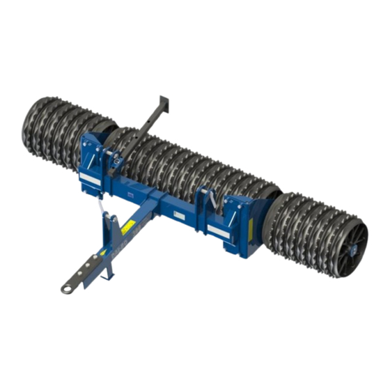
COMBIFLEX is a robustly-constructed drum with the following structure: • The machine is built up of one section, a main frame. • COMBIFLEX is constructed in such a way that goods of up to Ø61 cm in diameter can be mounted. -
Page 10: Connecting And Disconnecting Drawbar Eye
COMBIFLEX Connecting and disconnecting drawbar eye Connecting Fig. 1 The drum is connected to the tractor's permanent drawbar, whereby the drawbar eye (A) must be positioned between the drawbar forks. Fig 1 In- sert hitch pin. Secure the hitch pin with linchpin or similar. -
Page 11: Settings
COMBIFLEX Settings The drum has been factory set by the manufacturer, but a fine tuning will always be necessary before use. Many different adjustment possibilities make your drum more versatile and allow the opportunity to obtain optimal use from the machine. -
Page 12: Connecting And Disconnecting Of Lifting Arm
COMBIFLEX Connecting and disconnecting of lifting arm Connecting Connect the drum to the vehicle's three-point hitch at these points (A). Secure hitch pins with linchpin or similar. Disconnecting Remove hitch pins. In this way, the drum can be used both in fields and on roads. -
Page 13: Driving And Operating
COMBIFLEX Driving and operating Correct operation is important in order to get the optimal benefit from your drum. This applies not only to working in the field but also in terms of safety. Thus, it is im- portant to study the safety information relevant to the machine There must never be people present within the machinery's range of movement. -
Page 14: Maintenance
COMBIFLEX Maintenance Good maintenance ensures a long lifetime for the drum and thus optimal use of the machine. Lubrication points have therefore been mounted in the places where wear and tear are greatest. All screw connections must be tightened after the first day of work. Cotters and bolts are checked in order to avoid breakdown. -
Page 15: Replacements And Repairs
COMBIFLEX Replacements and repairs Safety is important with regards to all repair work on the drum. The following items must therefore be observed at all times, as well as the items under safety at the beginning of the instruction manual. -
Page 16: Uninstalling Of Drum Goods On The Outside Of Bearing Plates (A)
COMBIFLEX Uninstalling of drum goods on the outside of bearing plates (A) Repairs must be carried out on an even surface with the drum connected to a trac- tor. Replacing drum goods Fig. 3 1. The machine is mounted onto the tractor's hitch. - Page 17 COMBIFLEX Replacing drum goods 1. Loosen bolts/nuts (F). 2. Bearing plates incl. goods on the shaft (G) are removed from the main frame. 3. Goods on shaft incl. bearing plates are jacked up on an even surface and tilted. 4. Loosen the bolts (H).
-
Page 18: Additional Equipment
Additional Equipment Wheel frame for COMBIFLEX COMBIFLEX can be supplied with hydraulic wheel frame. The wheel frame is mounted with stud and linchpin (A) on the main frame, and the cylinder is mounted between the main frame and wheel frame with stud and cotter/linchpin (B). -
Page 19: Hydraulics
COMBIFLEX Hydraulics Connecting A double-acting hydraulic cylinder is required, which is used to raise/lower the wheel frame. Cylinder name Colour Outlet Function Tilting cylinder White Double-acting Tilt the wheel frame up from the ground and down into working position. • Make sure the hydraulic hoses have not been crushed. -
Page 20: Maintenance
COMBIFLEX Maintenance Good maintenance ensures a long lifetime for the drum and thus optimal use of the machine. Lubrication points have therefore been mounted in the places where wear and tear are greatest. All screw connections must be tightened after the first day of work. Cotters and bolts are checked in order to avoid breakdown. -
Page 21: Adjustments
COMBIFLEX Adjustments Wheels The wheel bearings must be lubricated and adjusted once a year. Similarly, the cor- rect tyre pressure must also be ensured (see recommended pressure on the tyre). Adjustments and lubrication of wheel bearings 1. The hub cap is removed. -
Page 22: Replacements And Repairs
COMBIFLEX Replacements and repairs Safety is important with regards to all repair work on the drum. The following items must therefore be observed at all times, as well as the items under safety at the beginning of the instruction manual. - Page 23 COMBIFLEX After mounting, activate the cylinder by folding and unfolding until a little water comes out of the cylinder. The cylinder is then activated in the opposite way until the cylinder is back in the starting position. The cylinder sometimes moves in this way.
-
Page 24: Gasket Set
COMBIFLEX Gasket set Replacement of gasket set REMOVAL: 1. Empty the cylinder of oil (this can be done by using the air pressure to move the piston backwards and forwards in order to push the oil out). 2. Move the piston in the middle position, whereby the end cap (pos. 3) is un- screwed from the cylinder tube (pos. -
Page 25: Uninstalling/Installing Of Wheels
COMBIFLEX Uninstalling/installing of wheels When uninstalling the wheel, unhinge the drum with the wheel frame raised. The wheels will thus be free of the ground. The wheel nuts are removed and the wheel can be replaced. After mounting the new wheel, screw the nuts on and tighten with a "firm hand". - Page 26 COMBIFLEX Hydraulics diagram for COMBIFLEX wheel frame 91134 1.0 mm Tractor pump and valve (vencil) Tilting cylinder white Page 26...
-
Page 27: Warranty
COMBIFLEX Warranty DALBO A/S provides a 1 year warranty on all new machines sold by an authorised DALBO dealer. The war- ranty is valid for 1 year calculated from the deliver date to the end user. The warranty covers fixing material and production faults. -
Page 28: Disposal
COMBIFLEX Disposal Unhinge the drum. It is crucial to release the pressure from all the cylinders. When mounting/dismounting, attention should be directed towards the weight on the part in question. Which is why it is important to support this section underneath or with rigging, so that there is no danger of falling. -
Page 29: Spare Parts
COMBIFLEX Spare parts Page 29...
Need help?
Do you have a question about the COMBIFLEX and is the answer not in the manual?
Questions and answers