Table of Contents
Advertisement
Quick Links
Advertisement
Table of Contents

Related Manuals for DALBO GREENLINE 300


Summary of Contents for DALBO GREENLINE 300
- Page 1 GREENLINE GREENLINE 300 Serial no.: 100-XXX...
- Page 3 Congratulations on the purchase of your new GREENLINE. For safety reasons and to achieve optimum service from the product, please read the User Guide before use. © Copyright 2002. All rights reserved, DALBO A/S This product has: Type no.: Serial no.:...
-
Page 5: Table Of Contents
Table of Contents SAFETY ............................7 ..............................7 ENERAL ..............................8 YDRAULICS ..............................8 SSEMBLY ..........................8 AINTENANCE AND REPAIR ............................9 OAD TRANSPORT .............................9 ORRECT USE TECHNICAL DATA ......................... 10 HOW TO USE THIS MANUAL ......................11 ............................... 11 ELIVERY USES ............................12 CONNECTING AND DISCONNECTING .................... 13 ............................ - Page 6 REPLACEMENT ANDREPAIRS ....................... 23 ............................23 YDRAULICS Replacing extend cylinder for retracting side sections ............23 Replacing gasket set for extend/retract cylinder ..............24 Replacing gaskets on raise/lower cylinder ................26 Replacing harrow depth-adjustment cylinder ................. 27 Replacing gasket set for depth adjustment ................27 .........................
-
Page 7: Safety
GREENLINE Safety This symbol appears in the instruction manual each time there is a safety warning concerning your safety, the safety of others or functionality of the machine. All safety instructions must be observed and made available to all users of the ma- chine. -
Page 8: Hydraulics
GREENLINE Hydraulics • Lower machine fully for any repair work on the hydraulic system. Relieve hy- draulic pressure, switch engine off and remove ignition key. • Clean hydraulic connections thoroughly before reconnecting. When connecting hydraulic hoses to tractor hydraulics, ensure they are not under pressure. •... -
Page 9: Road Transport
GREENLINE Road transport • All safety and warning precautions mandatory by law must be fitted and tested before transporting the machine on public roads. The driver is responsible for correct lighting and warning signs in accordance with traffic regulations. • Check with local traffic authorities whether transport on public roads is allowed given the machine's dimensions. -
Page 10: Technical Data
GREENLINE Technical data GREENLINE 300 Size (effective cm) Min. HP (recommended) 50 HP Gross weight kg: 1,260 kg Gross, incl. Water kg: 2,240 kg Sections (pcs.) Axles (pcs.) Wheels 11.5/80 x 15.3 Accessories Levelling bar (kg) Harrow (kg) Grass sowing system Wheels 400/60 x 15.5 Twin... -
Page 11: How To Use This Manual
GREENLINE How to use this manual The sequence of subject matter in this manual can seem illogical. Please refer to the table of contents for page numbers for individual items. The manual is divided into 5 main sections: • Safety •... -
Page 12: Uses
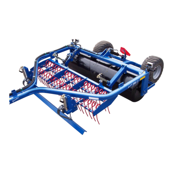
GREENLINE 300 GREENLINE can be fitted with accessories such as hydraulic harrow and for the care or sowing of grass. The levelling bar's main purpose is to level molehills and the like. The harrow aerates the soil by removing old grass from the roots. -
Page 13: Connecting And Disconnecting
GREENLINE Connecting and disconnecting Connecting Fig. 2 Connect roller to the tractor's fixed towbar, where drawbar (A) must fit between the towbar forks. Insert pin and raise leg. Remove and insert leg in transport socket.(B) • Remember to secure towbar pin with split pin or the like. •... -
Page 14: Setting Up
GREENLINE Setting up The roller is supplied with factory settings, but fine adjustment will always be re- quired before use. Numerous adjustment options make the roller more flexible and ensure maximum use. Adjusting drawbar height To achieve uniform rolling, the bar (A, Fig. 3) on the mid-section must be parallel with the ground and the drawbar (B, Fig. -
Page 15: Filling Water
GREENLINE Filling water Fig. 5 Turn roller until plug is at top. Turn roller until plug is at an angle rela- tive to the ground to achieve desired level of water if a full roller is not re- quired. Drain water before winter if no antifreeze is added. -
Page 16: Operation
GREENLINE Operation Correct operation is vital for optimum use of the roller. This applies to working in the field and for safety. Always ensure you are fully familiar with all safety aspects of the machine. Operating position Tractor must be parked when preparing operating position. ... -
Page 17: Troubleshooting
GREENLINE Troubleshooting Table 3. Fault Cause Remedy Hydraulics not wor- • Cylinder • Release hydraulic handle on cylin- handle king. locked. der. (see "Operation") • Hoses • Fit hydraulic hoses correctly in trac- coupling. tor coupling. • Pilot • Remove valve and clean parts. operated non-return valve •... -
Page 18: Accessories
GREENLINE Accessories GREENLINE can be fitted with a range of accessories to suit requirements. • Levelling bar • Harrow • Sowing system • Light • Large 400mm twin wheels. Levelling bar The advantage of the levelling bar is that it is mounted directly on the harrow sec- tion, allowing it to follow the ground contours. -
Page 19: Harrow
GREENLINE Harrow Hose markings Table 5. Hose markings Cylinder name Colour Outlet Function Depth adjustment Green Double acting Adjusts harrow depth. Adjusting angle of tines Fig. 8 Harrow depth is hydraulically adjusta- ble. The angle of the harrow section is adjusted manually on the handle (A). - Page 20 GREENLINE Assembly Fig. 9 Fit forward-acting arms (A) first. Push harrow frame (B) under main frame and secure on arms. (A) For more details, see spare parts dra- wing. Side 20...
-
Page 21: Maintenance
GREENLINE Maintenance Good maintenance ensures long service life and optimum use. Grease nipples are fitted where wear is heaviest. Tighten all screw connections after first working day. Check all split pins and bolts to avoid mechanical failure. Check hydraulic system for leaks. Lubrication Fig. -
Page 22: Adjustment
GREENLINE Adjustment Wheels Lubricate and adjust wheel bearings at least once annually. Check tyre pressures (see recommended pressure on tyre). Adjustment and lubrication of wheel bearings 1. Remove hub caps. 2. Remove split pin. 3. Tighten castle nut 1/6th of a turn until hole aligns with axle. Turn wheel, check for resistance. -
Page 23: Replacement Andrepairs
GREENLINE Replacement andrepairs Safety is vital for all repair work on the roller. Always observe the following points, plus those under Safety First in the instruction manual. When replacing cylinders, always fill new cylinder with oil before pressurising sys- tem. -
Page 24: Replacing Gasket Set For Extend/Retract Cylinder
GREENLINE Activate extend/retract cylinders after fitting until they show a little movement. Reverse cylinders until they return to start position. Move cylinders backwards and forward several times. Raise roller fully onto wheels, extend side sections fully to bleed system. Ensure no personnel are within the extension radius of the side sections. Replacing gasket set for extend/retract cylinder Fig. - Page 25 GREENLINE Assembly 1. Fit new gaskets (pos. 2+4+7+8+9) in upper part and collar shoe. Remember to check gaskets are facing the right way. 2. Lubricate thread in upper part (pos. 3) with oil. 3. Fit upper part (pos. 3) on ram shaft. 4.
-
Page 26: Replacing Gaskets On Raise/Lower Cylinder
GREENLINE Replacing gaskets on raise/lower cylinder Fig. 33 1. Drain oil from cylinder by moving ram carefully backwards and forwards. 2. Extend ram to centre position. Unscrew upper part (pos. 3) from cylinder tube (pos. 1). Use special tool to remove upper part. If upper part is stuck, heat front of upper part. -
Page 27: Replacing Harrow Depth-Adjustment Cylinder
GREENLINE Replacing harrow depth-adjustment cylinder Fig. 13 1. Lower roller to ground 2. Lower harrow, depressurise hydraulic system. 3. Disconnect hoses from cylin- der. 4. Remove split pins and pins (B) 5. Fit new or repaired cylinder (A) 6. Remember to replace split pins in pins Activate depth-adjustment cylinders up and down a few times after fitting and with roller lowered, to bleed system. -
Page 28: Removal/Fitting Wheel
GREENLINE Assembly 1 Fit new gaskets (pos. 5+6+7+8+9) in upper part, plus collar shoe. 2 Lubricate thread in upper part (pos. 3) and cylinder tube (pos. 1) with grease or oil. 3 Fit upper part (pos. 3) on ram shaft. Fit collar shoe (pos. -
Page 29: Removing Steel Roller
GREENLINE Assembly 1. Fit bearing outer rings pos. 17+18 in hub housing pos. 22 2. Fit seal ring pos. 16. 3. Fit bearing inner ring pos. 18 on axle pos. 2 and fit axle in hub housing 4. Fit bearing inner ring pos. 17 on axle pos. 2 5. -
Page 30: Scrapping
GREENLINE Scrapping Machine must be lowered. It is essential that all cylinders are removed. Beware of the weight of any given part when removing or disassembling. All parts must be supported or lifted to avoid danger of falling. Disconnect hydraulic hoses and cylinders and drain oil. Collect oil in container to avoid pollution. -
Page 31: Hydraulic Diagram
GREENLINE Hydraulic diagram Fig. 39 Side 31... -
Page 32: Spare Parts
GREENLINE Spare parts Side 32...
Need help?
Do you have a question about the GREENLINE 300 and is the answer not in the manual?
Questions and answers