Sign In
Upload
Download
Table of Contents
Contents
Add to my manuals
Delete from my manuals
Share
URL of this page:
HTML Link:
Bookmark this page
Add
Manual will be automatically added to "My Manuals"
Print this page
×
Bookmark added
×
Added to my manuals
Manuals
Brands
DALBO Manuals
Farm Equipment
MAXIROLL 530
Manual
DALBO MAXIROLL 530 Manual
Hide thumbs
1
2
3
4
Table Of Contents
5
6
7
8
9
10
11
12
13
14
15
16
17
18
19
20
21
22
23
24
25
26
27
28
29
30
31
32
33
34
35
36
37
38
39
page
of
39
Go
/
39
Contents
Table of Contents
Troubleshooting
Bookmarks
Table of Contents
Table of Contents
Safety
General
Hydraulic System
Hitching
Maintenance and Repairs
Transport
Correct Use
Technical Data
How to Use this Manual
Delivery
Application
Hitching and Unhitching
Hitching
Hydraulic System
Unhitching
Adjustments and Settings
Adjusting Hitch Height
Adjusting the Middle Section
Adjusting Wing Fold Stop
Operating and Driving Instructions
Unfolding and Folding
Unfolding
Folding
Adjusting Hydraulic Weight Transfer
Too Much Pressure
Too Little Pressure
Travel Speed
Power Requirements
Troubleshooting
Options
Crackerboard
Power Requirements
Hose Markings
Adjusting Tine Angle
Operating and Driving Instructions
Mounting after Delivery
Locking Kit
Maintenance
Lubrication
Adjustment
Adjusting the Rings
Wheels
Wearing Points
Hydraulic System
Replacements and Repairs
Hydraulic System
Changing Wing Fold Cylinders
Replacing Wing Fold Cylinder Seals
Assembly
Changing Tilting Cylinder
Replacing Tilting Cylinder Seals
Assembly
Changing Crackerboard Depth Adjustment Cylinder
Replacing Depth Adjustment Cylinder Seals
Assembly
Dismounting/Mounting of Wheels
Changing Wheel Bearings
Dismounting Roller Axle
Changing Wing Axles
Mounting of Axle with Roller Rings
Changing the Middle Axle
Changing Axle, Bearings or Roller Rings
Scrapping
Hydraulic System Diagram
Spare Parts
Advertisement
Quick Links
Download this manual
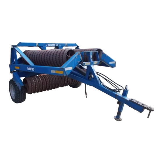
MAXIROLL
GB
530, 630, 760, 830
Serial no. 100-XXX
Table of
Contents
Previous
Page
Next
Page
1
2
3
4
5
Advertisement
Table of Contents
Need help?
Do you have a question about the MAXIROLL 530 and is the answer not in the manual?
Ask a question
Questions and answers
Related Manuals for DALBO MAXIROLL 530
Farm Equipment DALBO CULTILIFT 300 Manual
(25 pages)
Farm Equipment DALBO TRIMAX 520 User Manual
(42 pages)
Farm Equipment DALBO 300 Manual
(26 pages)
Farm Equipment DALBO TRIMAX 410 Lift User Manual
(41 pages)
Farm Equipment DALBO MAXIROLL 1030 Manual
(42 pages)
Farm Equipment DALBO MAXIROLL 950 Manual
(40 pages)
Farm Equipment DALBO MAXIROLL 630 Manual
(39 pages)
Farm Equipment DALBO MAXIROLL 830 Manual
(39 pages)
Farm Equipment DALBO MINIMAX 450 User Instructions
(49 pages)
Farm Equipment DALBO 300 Manual
Front-mounted grubber (25 pages)
Farm Equipment DALBO AXR-H Manual
(50 pages)
Farm Equipment DALBO ROLLOMAXIMUM XL Manual
(42 pages)
Farm Equipment DALBO MAXICUT Manual
(30 pages)
Farm Equipment DALBO MEGAROLL 2130 Manual
(38 pages)
Farm Equipment DALBO GREENLINE 300 Manual
(32 pages)
Farm Equipment DALBO POWERROLL 1430 Manual
(34 pages)
This manual is also suitable for:
Maxiroll 630
Maxiroll 760
Maxiroll 830
Table of Contents
Print
Rename the bookmark
Delete bookmark?
Delete from my manuals?
Login
Sign In
OR
Sign in with Facebook
Sign in with Google
Upload manual
Upload from disk
Upload from URL


Need help?
Do you have a question about the MAXIROLL 530 and is the answer not in the manual?
Questions and answers