
Related Manuals for DALBO MINIMAX 950


Summary of Contents for DALBO MINIMAX 950
- Page 1 MINIMAX User instructions Date of publication: 01/2021 Date printed: 01/2021 Language: Type: MINIMAX 950 Product no.: MINIMAX 950 Serial no.: 56270-xxxxx...
- Page 3 Congratulations on your new drum. For safety reasons and for optimal use from your machine, you should read through the user manual thoroughly before you take it into use. © Copyright 2002. All rights reserved DALBO A/S Your drum has: Type no.: Series no.:...
-
Page 4: Table Of Contents
Table of Contents INTRODUCTION AND IDENTIFICATION OF SERIAL NUMBER ............6 ............................ 6 NFORMATION ......................... 6 OCATION OF USER MANUAL ....................... 7 OCATION OF SERIAL NUMBER ........................7 ARRANTY PROVISION SAFETY ............................... 8 ............................8 ENERAL ............................. 10 OISE LEVEL ............................ - Page 5 MINIMAX Hose markings .......................... 25 Adjustment of the teeth's angle and depth ................25 Driving and operating ....................... 25 Retrofitting ..........................26 MAINTENANCE ..........................28 ............................ 28 UBRICATION ..........................29 DJUSTMENTS Adjustment of fittings ....................... 29 Wheels ............................29 Worn out parts ......................... 30 .............................
-
Page 6: Introduction And Identification Of Serial Number
• If there are doubts regarding reading the user guide or concerning the general use and safety of the drum, it is very important to stop its use and contact the DALBO A/S. Location of user manual Fig. 1... -
Page 7: Location Of Serial Number
Year of manufacture. CE imprinting. Warranty provision By default, your MINIMAX is delivered with a 2-year warranty from the date of delivery. DALBO A/S shall bear no liability for damage caused by the im- proper use of the drum. Page 7... -
Page 8: Safety
MINIMAX Safety You will see this symbol in the instruction manual each time advice is given about your safety, the safety of other users, or the functional safety of the machine. All safety instructions must be observed and made available to all users of the machine. - Page 9 Remove the white foil sticker from the label and stick the label onto the new part. • You can order a new safety label from the DALBO A/S • There should be no passerby around the machine during work or trans- portation.
-
Page 10: Noise Level
MINIMAX • This machine is usually used during the day, but should it be, exceptional- ly, necessary to use the machine at night or in conditions of reduced visi- bility the lighting system supplied with the tractor must be used. •... -
Page 11: Mounting
MINIMAX • For hydraulic systems with built-in pilot-controlled non-return valves, it can be difficult to completely remove the pressure. You should hold a cloth around the fitting/part that is being removed to catch any oil that may leak. • After repairs on the hydraulic system have been completed, all air must be completely removed from the system. -
Page 12: Driving On Roads
MINIMAX Driving on roads • When driving on public roads, all safety arrangements and warnings re- quired by law must be installed and tested. The driver is responsible for the correct use of lights, brake systems and traffic signs in accordance with traffic laws. -
Page 13: Technical Data
MINIMAX Technical data MINIMAX 950 Size [cm] HP (recommended) 160-220 Gross Weight [kg]: • Cambridge 50 5215 • Cambridge 55 6090 • Crosskill 53 4580 • Cross Combi 50 5340 • Cross Combi 55 6410 Sections (pieces) Hydraulic require- ments:... -
Page 14: How To Read The Instruction Manual
Incorrect rigging and lifting can cause serious damage to the machine and to persons around it. DALBO does not accept liability for damage in connection with inappro- priate or incorrect rigging and lifting. Page 14... -
Page 15: Use
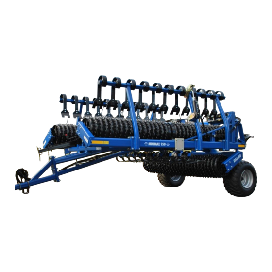
MINIMAX 950 As a drum, MINIMAX 950 is used before sowing to crush tubers as well as af- ter sowing to improve sprouting and push down stones. The MINIMAX 950 can be optionally fitted with hydraulic crackerboards. The main application of the crackerboard is in preparing the soil for sowing. -
Page 16: Connecting And Disconnecting
MINIMAX Connecting and disconnecting Connecting Fig. 3 The drum is connected to the tractor's fixed drawbar, where the towing eye (A) must be between the drawbar's forks. The lever is inserted, the sup- port leg raised and placed in the working position (B) ... -
Page 17: Settings
MINIMAX Settings The drum is factory set at delivery, but fine tuning will always be necessary before use. Many different adjustment options make your drums more ver- satile and allow the potential to gain optimal use of the machine. In order to achieve uniform pressure on the ground, the bar must be adjust- ed correctly for the tractor concerned. -
Page 18: Adjustment Of Central Section
MINIMAX Adjustment of Central Section Fig. 6 With the MINIMAX unfolded (see “Driving and operating”) check if the bolts (A) have approx. 10 mm air to the pipe (B). The central section must be hori- zontal to achieve the best result in the field. -
Page 19: Driving And Operating
MINIMAX Driving and operating Proper operation is important in order to get optimal performance from your drum. This applies not only to working in the field but also in terms of safety. It is therefore crucial that you have thoroughly read the safety precautions that cover the machine. -
Page 20: Folding
MINIMAX Folding Fig. 11 1. The unfolded and folded cylin- ders (marked: Red) are acti- vated, so that the outside of the side sections (A) are lifted as much as possible. Fig. 12 2. The tilt cylinders (marked: White) are activated to full length and the drum is tilted free of the ground Fig. -
Page 21: Adjustments Of Hydraulic Weight Transfer
MINIMAX Adjustments of hydraulic weight transfer The hydraulic weight transfer distributes the weight evenly on the drum sec- tions. 1. After the drum is unfolded, pressure is taken out of the unfolded and folded cylinders (marked: Red), after which the cylinders' control lev- er is activated in the opposite direction. -
Page 22: Driving Speed
MINIMAX Failure to put the machine in float position is considered improper use and could, in a worst case scenario, cause a break in the frame. Driving speed It is recommended that the machine be driven at 6-10 km/h, but driving should always be done according to conditions. -
Page 23: Troubleshooting
MINIMAX Troubleshooting Problem Cause Remedy • Too little pressure • The hydraulic lever for unfold- The central sec- tion is pressing is being trans- ing/folding is activated in such a too much ferred to the side way that it is creating more pres- sections sure on the side sections (see “Driv- ing and Operating”). -
Page 24: Additional Equipment
MINIMAX Additional Equipment It is possible to equip the MaxiMax 950 with different types of extra equip- ment • Crackerboards with bowed parts • Gabions • Light Sets • Air brakes • Hydraulic brakes Crackerboard The clear advantages of the crackerboards are that the teeth can be moved individually so that they give after meeting with local resistance. -
Page 25: Hose Markings
MINIMAX Hose markings Table 4. Hose markings Cylinder name Col- Outlet Function Depth adjustment / Gree Double-acting Adjusts the cracker- Angle adjustment board's working depth Adjustment of the teeth's angle and depth Fig. 16 The crackerboard's working depth and angle are hydraulically (A) ad- justable. -
Page 26: Retrofitting
MINIMAX Retrofitting The crackerboard can be mounted at the factory, but it can also be delivered later if the need arises. For mounting, a crane or similar auxiliary equipment will be re- quired. Fig. 18 1 Unfolding the MINIMAX. 2 The mid-section is mounted in the flanges (A). - Page 27 MINIMAX It is important to ventilate the system thoroughly in order to prevent personal injury. Which is why you should move the cylinders right out into the outer positions a couple of times. Page 27...
-
Page 28: Maintenance
MINIMAX Maintenance Good maintenance ensures a long life for the drum and therefore optimal use of the machine. Which is why grease fittings have been installed in plac- es where wear is greatest. All screw connections must be tightened after the first day of work. Cotter pins and bolts should be checked to avoid breakdowns. -
Page 29: Adjustments
By moving the stop rings on the shaft, the fittings can be clamped together to re- move any dirt and wear can be minimised. Adjustment of fittings is best done with the MINIMAX 950 folded. Fig. 23 1 The bolts (A) are loosened and... -
Page 30: Worn Out Parts
MINIMAX Worn out parts Fig. 24 The slides are factory-fitted in the upper holes on the tooth. The slides must be moved to the lower holes (A) before wear starts to appear on the teeth. After the slides are worn out. Positioned in the lower holes, replace the slides so that no wear occurs on the crackerboard. -
Page 31: Replacement And Repairs
MINIMAX Replacement and repairs Safety is crucial in regard to all repair work on the drum. The following points must therefore be observed at all times, as well as the points under safety at the beginning of the instruction manual. When replacing cylinders, always fill the cylinder with oil before subjecting it ... - Page 32 MINIMAX the outer positions to air out the system. There must never be people within the machine's operating radius. Replacement of the gaskets DISMANTLING: 1. Empty the cylinder of oil, (if necessary, use compressed air to move the piston back and forth to push the oil out). 2.
- Page 33 MINIMAX 8. Screw the cap on and tighten. Page 33...
-
Page 34: Changing The Tilt Cylinder
MINIMAX Changing the tilt cylinder Fig. 27 The drum is unfolded and lowered onto the base (working position). The pressure is removed from the tilt cylinders (A). 1. The hoses are disconnected from the cylinder. 2. The cylinder is supported. 3. -
Page 35: Change The Gaskets On The Tilt Cylinder
MINIMAX Change the gaskets on the tilt cylinder Fig. 28 1. The cylinder is emptied of oil by moving the piston carefully back and forth. 2. Move the piston into the centre position, after which the end cap (pos. 3) is unscrewed from the cylinder tube (pos. -
Page 36: Additional Equipment - Changing The Cylinder To Crackerboard
MINIMAX Additional Equipment - Changing the cylinder to crackerboard Fig. 29 1. MINIMAX is unfolded while rest- ing on the ground. 2. The crackerboard is lowered and the pressure is removed from the hydraulic system. 3. The hoses are disconnected from the cylinder. - Page 37 MINIMAX 4 The sleeve (pos. 4) is removed from the piston rod (pos. 5). 5 The cap (pos. 3) is removed from the piston rod (pos. 5). 6 The gaskets are removed. 7 All parts are cleaned and checked for chips, burrs etc. Check for rust around the scraper ring in the cap.
-
Page 38: Uninstalling/Installing Of Wheels
MINIMAX Uninstalling/installing of wheels To uninstall the wheels, unfold the drum with the rings resting on the base. The wheels will then be clear of the ground. The wheel nuts are removed and the wheel can be replaced. After mounting the new wheel, screw the nuts on and tighten with a “firm hand”. -
Page 39: Dismantling The Drum Body
MINIMAX Dismantling the drum body The repair is performed on a flat surface with the drum connected to a trac- tor and unfolded with the rings resting on the ground. It would be a great help to have a crane or something similar available for both the dismantling and assembly. - Page 40 MINIMAX from the drum. 6. Mounting is carried out in re- verse order The hydraulic system must not be activated when there are persons within the machine's operating radius. Page 40...
-
Page 41: Disposal
MINIMAX Disposal The drum must be unfolded. It is crucial that the pressure is released from all the cylinders. When dismantling/assembling, attention should be directed towards the weight on the part in question. It is therefore important that this part be supported or lifted up, so there is no risk of collapse or overturning. -
Page 42: Hydraulics Diagram
MINIMAX Hydraulics diagram Ground machine Fig. 34 MINIMAX 950 91806 91806 8040 X 350 8040 X 350 13315 13315 1.0 mm 1.0 mm 91806 91806 8040 X 350 8040 X 350 Manometer 27398 Kovira valve single Accumulator 1.0 L 25 Bars... -
Page 43: Additional Equipment - Crackerboard
MINIMAX Additional Equipment - Crackerboard Fig. 35 MINIMAX 950 Lamelplanke Crackerboard Grøn Green Grün Tractor pump and valve Page 43... -
Page 44: Spare Parts
MINIMAX Spare parts Page 44...
Need help?
Do you have a question about the MINIMAX 950 and is the answer not in the manual?
Questions and answers