
Subscribe to Our Youtube Channel
Related Manuals for DALBO MINIMAX 450


Summary of Contents for DALBO MINIMAX 450
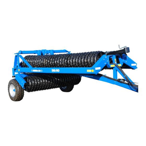
- Page 1 MINIMAX User instructions Date of publication: 01/2021 Date printed: 01/2021 Language: Type: MINIMAX 450-830 Product no.: MINIMAX 450-830 Serial no.: 50949-xxxxx...
- Page 2 - 2 -...
- Page 3 Congratulations on the purchase of your new roller. For safety reasons and to achieve optimum service from the product, please read the User Guide before use. © Copyright 2002. All rights reserved, DALBO A/S This product has: Type no.: Serial no.:...
-
Page 4: Table Of Contents
Table of Contents INTRODUCTION AND IDENTIFICATION OF SERIAL NUMBER ......... 6 ........................6 NFORMATION ....................6 OCATION OF USER MANUAL ....................7 OCATION OF SERIAL NUMBER ....................... 7 ARRANTY PROVISION SAFETY..........................8 ......................... 8 ENERAL ........................10 OISE LEVEL ........................10 YDRAULICS ........................ - Page 5 Driving and operation .................... 25 Retro-fitting ......................26 ..................28 ONNECTION WITH TOWING EYE MAINTENANCE ......................29 ........................29 UBRICATION ........................30 DJUSTMENT Adjustment of fittings .................... 30 Wheels ........................30 Tyre pressure ......................31 Worn out parts ....................... 32 ........................
-
Page 6: Introduction And Identification Of Serial Number
If there are doubts regarding reading the user guide or concerning the general use and safety of the drum, it is very important to stop its use and contact the DALBO A/S. Location of user manual Fig. 1... -
Page 7: Location Of Serial Number
Year of manufacture. CE imprinting. Warranty provision By default, your MINIMAX is delivered with a 2-year warranty from the date of delivery. DALBO A/S shall bear no liability for damage caused by the im- proper use of the drum. Page 7... -
Page 8: Safety
Safety You will see this symbol in the instruction manual each time advice is given about your safety, the safety of other users, or the functional safety of the machine. All safety instructions must be observed and made available to all users of the machine. - Page 9 Remove the white foil sticker from the label and stick the label onto the new part. You can order a new safety label from the DALBO A/S There should be no passerby around the machine during work or transpor- tation.
-
Page 10: Noise Level
This machine is usually used during the day, but should it be, exceptionally, necessary to use the machine at night or in conditions of reduced visibility the lighting system supplied with the tractor must be used. Verify the machine carefully before starting it up. ... -
Page 11: Mounting
For hydraulic systems with built-in pilot-controlled non-return valves, it can be difficult to completely remove the pressure. You should hold a cloth around the fitting/part that is being removed to catch any oil that may leak. After repairs on the hydraulic system have been completed, all air must be completely removed from the system. -
Page 12: Driving On Roads
Driving on roads When driving on public roads, all safety arrangements and warnings re- quired by law must be installed and tested. The driver is responsible for the correct use of lights, brake systems and traffic signs in accordance with traffic laws. -
Page 13: Technical Data
Technical data MINIMAX Table 1. Technical data Size [cm] HP (maximum) Gross Weight [kg]: Cambridge 50 2190 2800 3145 4070 4160 Cambridge 55 2610 3290 3720 4760 4930 Cambridge 60 4515 5875 Crosskill 53 1860 2325 2660 3545 3650... -
Page 14: How To Read The Instruction Manual
(See page 9, section on “General Security”) Incorrect rigging and lifting can cause serious damage to the machine and to persons around it. DALBO A/S does not accept liability for damage in connection with inap- propriate or incorrect rigging and lifting. Page 14... -
Page 15: Use
This is a standard roller, designed for rolling and levelling ploughed and sown areas. Rolling is intended on farming areas where better soil compaction is needed and to avoid the soil to dry out by extreme dry conditions. Rollers equipped with crackerboard is able to level ploughed areas with a per- fect result. -
Page 16: Connecting And Disconnecting
Connecting and disconnecting Connecting Fig. 5 The drum is connected to the tractor’s fixed drawbar, where the towing eye (A) must be be- tween the drawbar’s forks. The lever is inserted, the sup- port leg raised and placed in the working position (B). ... -
Page 17: Drawbar
Drawbar Some countries require a special turn able drawbar like shown on the picture below. Setup on this drawbar type must be done exactly the same way than described in section “Setting up” on page 18. Page 17... -
Page 18: Settings
Settings The drum is factory set at delivery, but fine tuning will always be necessary before use. Many different adjustment options make your drums more versa- tile and enable optimal use of the machine. In order to achieve uniform pressure on the ground, the draw-bar must be adjusted correctly for the tractor concerned. - Page 19 To ensure correct settings, it is important that the machine is on a horizontal surface when the setting is set. Page 19...
-
Page 20: Driving And Operation
Driving and operation Proper operation is important in order to get optimal performance from your drum. This applies to both work in the field and in terms of safety. It is there- fore crucial that you have thoroughly read the safety precautions that cover the machine. -
Page 21: Folding
Folding Fig. 10 1. The foldable and unfoldable cylinders (A) (marked: Red) are activated so that it is as short as possible. Fig. 11 2. The tilt cylinders (marked: White) are activated to full length and the drum is tilted away from the ground. -
Page 22: Driving Speed
Driving speed It is recommended that the machine is driven at 6-10 km/h, and always in compliance with weather conditions. If speed is increased, wear will also increase, especially under dry conditions. There is also a risk of damaging the rings by driving at excessively high speeds under adverse conditions. -
Page 23: Troubleshooting
Troubleshooting Problem Cause Fixing Too little pres- The hydraulic handle for folding The central sec- tion is pressing sure is being out/in is activated so that it is in too much transferred to the float position. the side sec- tions ... -
Page 24: Extra Equipment
Extra equipment It is possible to equip the MINIMAX 450-830 with different types of extra equipment. Cracker boards with bowed worn parts Gabions Light Sets Air brakes Hydraulic brakes Lift bar Cracker boards The clear advantages of the cracker boards are that the teeth can be moved individually so that they give after meeting resistance locally. -
Page 25: Hose Labels
By moving the least amount of soil possible, this reduces fuel consumption while reducing wear on the material. Hose labels Table 6. Hose labels Cylinder name Colour Outlet Function Depth adjustment/ Green Double-acting Adjusts the cracker Angle adjustment board’s working depth Adjustment of the teeth’s angle and depth Fig. -
Page 26: Retro-Fitting
(C). Finally, tighten (D). Fig. 17 3 Mount the side sections ac- cording to the drawing pro- vided by the DALBO A/S (A). 4 Mount the hydraulic cylin- ders (A). Fig. 18 5 Mount the middle hydraulic cylinder as shown (A) with the nipples facing down- wards. - Page 27 Fig. 19 7 Mount the hoses according to the diagram shown in the “Hydraulic diagram” section. 8 The hoses are fastened to the hose holders (arrow) (not all hose holders can be seen in the figure). It is important to ventilate the system thoroughly in order to prevent personal injury.
-
Page 28: Connection With Towing Eye
Connection with towing eye Fig. 20 The drum is connected to the tractor’s fixed drawbar, where the towing eye (A) should be between the tractor’s draw- bar. Insert a cotter key or bolt; raise the support leg and set in working position (B). -
Page 29: Maintenance
Maintenance Good maintenance ensures a long life for the drum and therefore optimal use of the machine. Which is why grease fittings have been installed in places where wear is greatest. All screw connections must be tightened after the first day of work. Cotter pins and bolts should be checked to avoid breakdowns. -
Page 30: Adjustment
All lubrication points should be greased at least once a year. It is also rec- ommended to spray protruding piston rods with oil when the drum has been cleaned, washed and parked for the longer term at the end of the sea- son. -
Page 31: Tyre Pressure
Tyre pressure In the tables below you can see the load, speed and tyre pressure relative to each other for the different tyre combinations. 300/80-15.3 Starco 400/60-15.5 Alliance 10.0/75-15.3 Alliance Page 31... -
Page 32: Worn Out Parts
Worn out parts Fig. 23 The wear parts are factory-fitted in the upper holes on the tooth. The wear slides must be moved to the lower holes (A) be- fore wear starts to appear on the teeth. After the wear parts are worn out. Positioned in the lower holes, replace the slides so that no wear occurs on the cracker board. -
Page 33: Replacements And Repairs
Replacements and repairs Safety is crucial in regard to all repair work on the drum. The following items must therefore be observed at all times, as well as all items under safety at the beginning of the instruction manual. When replacing the cylinders, always fill the cylinder with oil before subject- ... - Page 34 After mounting, the cylinders are activated for unfolding and folding until a small amount of movement can be felt in the cylinders. The cylinders are then activated in the opposite direction until the cylinders are back in the starting position. The cylinders are moved in this way a few times. The drum is then tilted up onto the wheels and the side sections move out completely into the outer positions to air out the system.
- Page 35 Replacement of the gaskets DISMANTLING: 1. Empty the cylinder of oil, (if necessary, use compressed air to move the piston back and forth to push the oil out). 2. Drive the piston to the centre position. The cap (pos. 3) is unscrewed 30 mm.
-
Page 36: Changing The Tilt Cylinder
Changing the tilt cylinder Fig. 26 The drum is unfolded and lowered onto the base (working position). The pressure is re- moved from the tilting cylinder (A). 1. The hoses are disconnected from the cylinder. 2. The cylinder is supported. 3. -
Page 37: Change Of Gasket Set On The Tilt Cylinder
Change of gasket set on the tilt cylinder Fig. 27 1. The cylinder is emptied of oil by carefully moving the piston back and forth. 2. Move the piston to the middle position, then unscrew the end cap (pos. 3) from the cylinder tube (pos. -
Page 38: Additional Equipment - Changing The Cylinder To The Cracker Board
Additional Equipment - Changing the cylinder to the cracker board Fig. 28 1. MINIMAX is unfolded while rest- ing on the ground. 2. The cracker board is lowered and the pressure is removed from the hydraulic system. 3. The hoses are disconnected from the cylinders. - Page 39 6 The gaskets are removed. 7 All parts are cleaned and checked for chips, burrs etc. Check for rust around the scraper ring in the cap. If this is the case remove it. Mounting 1 New seals and a sleeve are mounted. 2 The thread on the cap (pos.
-
Page 40: Removing/Mounting Wheels On The Road
Removing/mounting wheels on the road To remove a wheel on the road, hoist the drum with a strap and crane (A), or jack (B) as shown in the pictures below. The wheel will thus be free of the ground. The wheel nuts are removed and the wheel can be replaced. After installing the new wheel, screw the nuts on and tighten with a “firm hand”. -
Page 41: Replacing The Bearings
Replacing the bearings Fig. 31 1. The hub cap pos. 21 is removed. 2. The cotter pos. 20 is removed. 3. The castellated nut pos. 19 is re- moved. 4. The axle pos. 2 can now be re- moved. 5. The bearings pos. 17+18 are re- moved. -
Page 42: Dismantling The Drum Body
Dismantling the drum body Perform repairs on a flat surface with the drum connected to a tractor and unfolded with the rings resting on the ground. It would be very helpful to have a crane or something similar available for both the dismantling and assembly. Replacement of the drum body on the side sections If no crane is available, both axles on the side sections must be removed to prevent the drum from overturning. -
Page 43: Replacement Of The Centre Drum Body
Replacement of the centre drum body Fig. 33 1. Loosen the bolts (A). 2. The tilt cylinder is activated, the drum is tilted towards the wheels, the drum rings sup- port the base and the bolts are loose. 3. Remove the bolts. 4. -
Page 44: Disposal
Disposal The drum must be unfolded. It is crucial to release the pressure from all the cylinders. With disassembly/dismounting, attention should be directed towards the load on the part in question. It is therefore important that this part be sup- ported or lifted, to avoid risk of collapse or overturning. -
Page 45: Hydraulic Diagram
Hydraulic diagram: Page 45... - Page 46 Page 46...
- Page 47 Page 47...
-
Page 48: Spare Parts
Spare parts Page 48... - Page 49 Page 49...
Need help?
Do you have a question about the MINIMAX 450 and is the answer not in the manual?
Questions and answers