Table of Contents
Advertisement
Quick Links
Advertisement
Table of Contents

Subscribe to Our Youtube Channel
Related Manuals for DALBO MAXICUT 920


Summary of Contents for DALBO MAXICUT 920
- Page 1 MAXICUT Series no: 101163-XXXXXX...
- Page 3 Congratulations on your new MAXICUT. For safety reasons and to achieve the best possible use out of your machine, you should read through the user instructions carefully before taking the machine into use. © Copyright 2009. All rights reserved DALBO A/S. Your MAXICUT has: Type no.: Serial no.:...
-
Page 5: Table Of Contents
Table of Contents SAFETY ............................7 ..............................7 ENERAL ..............................8 YDRAULICS ............................8 NSTALLATION ..........................8 AINTENANCE AND REPAIR .............................8 RIVING ON ROADS .............................9 ORRECT USE TECHNICAL DATA ......................... 10 HOW TO READ THE INSTRUCTION MANUAL .................. 11 ............................... 11 ELIVERY DESCRIPTION OF THE MACHINE ....................12 LIMITATIONS IN THE USE OF THE MACHINE ................. - Page 6 Hose markings..........................29 Driving and operating ........................30 Retrofitting ............................ 30 MAINTENANCE ..........................31 ............................31 UBRICATION ............................33 DJUSTMENTS Wheels ............................33 Swivel stool ........................... 33 ............................. 34 ORN OUT PARTS ............................34 NIFE DRUMS ............................34 YDRAULICS REPLACEMENTS AND REPAIRS..................... 35 ............................
-
Page 7: Safety
• When the MAXICUT 920 is in transport position, it is important that the side sections are lowered in the transport hooks before driving on public roads. Likewise, this secures the control levers against accidental operation. -
Page 8: Hydraulics
MAXICUT Hydraulics • Prior to any repair work on the hydraulics unit, the machine's undercarriage must be low- ered, the pressure must be removed from the unit, the engine must be switched off and the ignition key must be removed. •... -
Page 9: Correct Use
MAXICUT • When transporting the machine, care must be taken not to exceed the total weight and axle load of the tractor and that the load on the front axle is not less than 20 per cent of the tractor's overall weight. In that case, use the front weight of the tractor. Correct use •... -
Page 10: Technical Data
MAXICUT Technical data Ground The plate Saw equipment MAXICUT 920 machine equipment 500L tank Working width (cm) HP (recommended 50–100 min) Sections (pieces) Wheels 700/40-22.5 700/40-22.5 700/40-22.5 Weight in kg: Without water approx. 10,000 1380 With water approx. 12,300 Hydraulic require-... -
Page 11: How To Read The Instruction Manual
MAXICUT How to read the instruction manual It is possible that the order in which the topics are listed does not appear as logical. Please refer to the table of contents, where the titles for the relevant topics can be found. The main points in the instruction manual are divided into 5 key sections: •... -
Page 12: Description Of The Machine
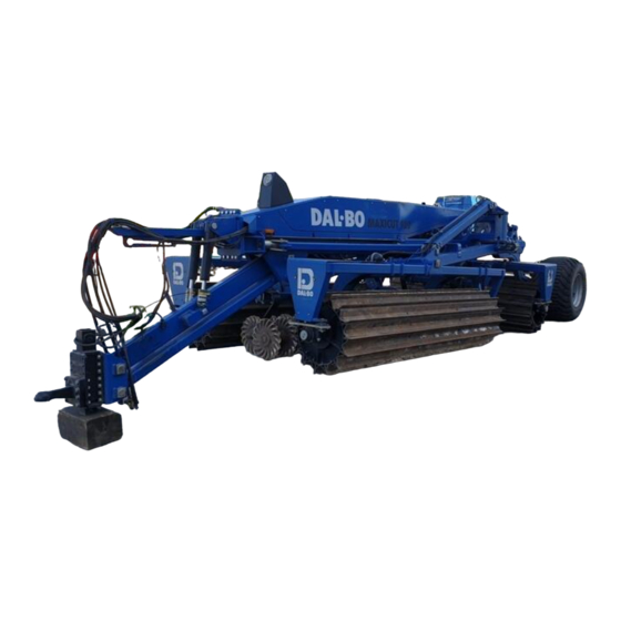
By default, there are strong bearings. MAXICUT 920 in work mode MAXICUT's intended purpose is harvesting, for example, corn, sunflower or rape seed. The ma- chine's total weight and the nature of the soil play a large part here. The machine is most effective when the knife-drum is completely filled with water and the soil is completely dry. -
Page 13: Limitations In The Use Of The Machine
MAXICUT Limitations in the use of the machine The following describes what the machine may/must not be used for: • The machine may only be used for tilling organic plant material in agricultural areas that have been culti- vated. Those areas to be tilled must have been subject to normal agricultural maintenance, i.e. without sig- nificant bumps or holes. -
Page 14: Connecting And Disconnecting
MAXICUT Connecting and disconnecting Connecting The MAXICUT 920 can be fitted with 2 different types of features. One feature designed for installing in the tractor's three-point suspension; the height adjust- ing via the suspension. The machine can also be fitted with a hydraulic feature that adjusts the height via hydraulics, as well as hydro-clips. -
Page 15: Disconnecting
MAXICUT Furthermore, the timing belt cannot be lowered if the tractor's motor is switched off. If the plate equipment is installed on the machine, 1 extra double-acting hydraulic outlet is required to adjust this. Hose markings Cylinder name Colour Outlet Function For lifting and adjusting the the plate equipment Green... -
Page 16: Settings
The main frame and knife drums will then also be horizontal in relation to each other. Fig. 4 Here you can see the MAXICUT 920 at work. The main frame is horizontal while the individual knife sections have the opportunity to move. -
Page 17: Adjusting The Side Frames
MAXICUT If the machine is installed with hydraulic pull, there are various adjustment options. It is pos- sible to adjust the cylinders (A) as there are different thicknesses of hydroclips with the ma- chine. It is also possible to move the feature up and down in 2 different flange plates (B and Fig. - Page 18 MAXICUT Fig. 7 It is important to make sure that the top rods are set against the spacers and that the angle is 90 degrees or slightly under so as not to damage the machine or un- fold the cylinders. Page 18...
-
Page 19: Driving And Operating
MAXICUT Driving and operating Proper operation is important in order to get optimal performance from your MAXICUT. This applies not only to working in the field but also in terms of safety. It is therefore crucial that you have thoroughly read the safety precautions that cover the machine. Unfolding and folding Unfolding and folding are conducted with the tractor in park. -
Page 20: Folding
MAXICUT It is extremely important that the hydraulic lever that goes to the hydraulic weight distribution of the machine is in float position during work in the ground so as not to damage the hydraulic system (the large cylinder lifting the side frames. The hose marked with: Red) ... -
Page 21: Turning In The Field Or Headland
MAXICUT Turning in the field or headland When one turns in the headlands and fails to raise the machine up on the timing belt, it is important to jump 1 to 2 pulls over. That means one must drive in every second or third pull to protect the machine and, in particular, bearings and rubber dampers. -
Page 22: Troubleshooting
MAXICUT Troubleshooting Problem Cause Trouble-shooting Adjust the pull to horizontal or with a lit- The pull is too strong tle tilt forward The central section (see "Tensile adjustment") is pressing too Too little or no pres- Adjust the pressure in the hydraulic sys- much sure in the hydraulic tem for hydraulic weight distribution... -
Page 23: Extra Equipment
MAXICUT Extra equipment It is possible to equip the MAXICUT 920 with different types of extra equipment if necessary. - Wave plates with different widths (wave heights) and design - Grass drums (Smooth steel drums for grass areas) - Mole planks (Primarily in combination with Grass Drums) -
Page 24: Power
MAXICUT Power The power requirement for driving with wave plates depends a lot upon the soil type, the working depth and the forward speed. Power requirements in [HP] wave plates Model Wave plates power requirements [ HP min. ] 50–100 Hose markings Hose markings Cylinder name... -
Page 25: Retrofitting
MAXICUT 0. Verify that the sections are completely lowered and the machine is unfolded and lowered to the ground. 1. Pressure is put on the plates, after which the lever is put into float position. If the machine is raised up on the timing belt during turning as recommended, the plates are lifted off the ground and one doesn't need to do anything else. -
Page 26: Grass Drums
The power requirement is very dependent on the type of soil and terrain as well as the speed. Guiding power requirement [ hp ] (without levelling) Model MAXICUT 920 with Grass drums Power requirement in [ HP ] 190–220 Driving and operating Once the grass drums are installed, it is recommended that the machine be driven at 6–10 km/h,... -
Page 27: Installation
MAXICUT Installation When replacing drums, a crane, truck or similar lifting equipment will be required. It is recommended that the drums be emptied of any water before disassembly. This is done both to facilitate the handling of the drums after disassembly, but also to secure them against frost. -
Page 28: Power
MAXICUT It is possible to equip the machine with mole planks, which are mainly intended to even out mole holes and other uneven grass areas. The mole plank is therefore mainly intended to be used in combination with the grass drums. Fig. -
Page 29: Hose Markings
MAXICUT It is possible to install saw equipment separately or in combination with one of the other pos- sible options. The saw equipment is installed with a hydraulic fan and has 16 outlets distributed over the working width. Fig. 16 Hose markings Hose markings Cylinder name... -
Page 30: Driving And Operating
MAXICUT Driving and operating Fig. 17 1. When filling the saw machine, use the ladder up to the platform. 2. After use, place the ladder (A) in the transport position and ensure that the transport latch (B) has been locked so that the ladder does not flap out while driving or transporting. -
Page 31: Maintenance
MAXICUT Maintenance Good maintenance ensures a long life for the MAXICUT and therefore optimal use of the ma- chine. Grease fittings have therefore been installed in places where wear is greatest. All screw connections must be tightened after the first day of work. Cotter pins and bolts should be checked to avoid breakdowns. - Page 32 MAXICUT Fig. 19 G ( and H ) I and J Page 32...
-
Page 33: Adjustments
MAXICUT Adjustments Wheels The wheel bearing must be lubricated and adjusted once a year. Also make sure you have the correct tyre pressure (see tyres). Adjustments and lubrication of wheel bearings 1. Hub cap is removed. 2. The cotter is removed. 3. -
Page 34: Worn Out Parts
MAXICUT Worn out parts Fig. 21 The factory blades are fitted with a pro- tective plate (A) between each to pro- tect the bolts and containers. The blades can be replaced as necessary, with 3 to 4 knives installed per row of every one of the 3 roller bearings. -
Page 35: Replacements And Repairs
MAXICUT Replacements and repairs Safety is crucial regarding all repair work on MAXICUT. The following items must therefore be observed at all times, as well as the items under safety at the begin- ning of the instruction manual. All maintenance and repair work on MAXICUT must be conducted only when the ma- chine is lowered to the ground or, is set in transport mode, the tractor has the break on, the engine is switched off and the ignition key is removed, so that the machine cannot move or start accidentally. -
Page 36: Installation
MAXICUT Fig. 23 1. The cylinder is emptied of oil by moving the piston carefully back and forth. 2. Move the piston in the middle position, then unscrew the end cap (pos. 3) from the cyl- inder tube (pos. 1). A special tool must be used to remove the cap. If the cap is stuck, it may help to warm up the front of the cap. -
Page 37: Changing The Timing Belt-Cylinder
MAXICUT Changing the timing belt-cylinder Fig. 24 1. The timing belt is lowered on solid surfaces and the pressure is taken off the timing belt-cylinder. 2. The hoses are installed on the cylin- der. 3. The cylinder is supported. 4. Cotter pins and nails are removed, and then the cylinder is free. -
Page 38: Change The Gaskets On The Timing Belt-Cylinder
MAXICUT Change the gaskets on the timing belt-cylinder Fig. 25 1. The cylinder is emptied of oil by moving the piston carefully back and forth. 2. Move the piston in the middle position, then unscrew the end cap (pos. 3) from the cyl- inder tube (pos. -
Page 39: Changing The Cylinder To Raising And Lowering The Side Sections
MAXICUT Changing the cylinder to raising and lowering the side sections Fig. 26 1. The pressure is taken off the cylinders (A). Ensure that no pressure is dis- played on the pressure gauge. 2. Ensure that the limiter-rail over the cyl- inder is not clogged. -
Page 40: Changing The Cylinder Gasket For Raising And Lowering The Side Sections
MAXICUT Changing the cylinder gasket for raising and lowering the side sections Fig. 27 1. The cylinder is emptied of oil by moving the piston carefully back and forth. 2. Move the piston in the middle position, then unscrew the end cap (pos. 3) from the cyl- inder tube (pos. -
Page 41: Change Cylinders For Hydraulic Pull
MAXICUT Change cylinders for hydraulic pull By replacing the cylinders with hydraulic pull. MUST keep the machine collapsed and lowered without strain on the pull. Fig. 28 1. The pull is supported. 2. The pressure is taken off the cylin- ders (A). -
Page 42: Replacement Of The Gaskets For Hydraulic Pull
MAXICUT Replacement of the gaskets for hydraulic pull Fig. 29 1. The cylinder is emptied of oil by moving the piston carefully back and forth. 2. Move the piston in the middle position, then unscrew the end cap (pos. 3) from the cyl- inder tube (pos. -
Page 43: Uninstalling/Installing Of Wheels
MAXICUT Uninstalling/installing of wheels For uninstalling wheels, the timing belt is lifted off the ground. The wheels will thus be free of the ground. The wheel nuts are removed and the wheel can be replaced. After installing the new wheel, screw the nuts on and tighten with a "firm hand". Next, lower the wheels so that they are touching the ground and tighten the nuts with 300 Nm. -
Page 44: Disassembly Of The Knife Drum
MAXICUT Disassembly of the knife drum The repair is performed on a flat surface with MAXICUT connected to a tractor and unfolded with all 3 knife drums resting on the ground. It would be a great help to have a crane or some- thing similar available for both the disassembly and installation. -
Page 45: Replacement Of The Knife
MAXICUT Replacement of the knife If no crane is available, both axles on the side sections must be removed to prevent the drum overturning. Fig. 32 1. The machine is folded out in work position. 2. Soil remaining (A) in between the knife blades must be cleaned/re- moved. -
Page 46: Disposal
MAXICUT Disposal MAXICUT must be unfolded. It is crucial to release the pressure from all the cylin- ders. With disassembly/dismounting, attention should be directed towards the weight on the part in question. It is therefore important that this part is supported or lifted up, so there is no risk of crashing/rolling over. -
Page 47: Spare Parts
MAXICUT Spare parts Page 47... -
Page 48: Warranty
MAXICUT Warranty DALBO A/S provides a 1 year warranty on all new machines sold by an authorised DALBO dealer. The warranty is valid for 1 year calculated from the delivery date to the end user. The warranty covers fixing material and production faults. -
Page 49: Hydraulics Diagram For Maxicut
MAXICUT Hydraulics diagram for MAXICUT Page 49...
Need help?
Do you have a question about the MAXICUT 920 and is the answer not in the manual?
Questions and answers