Sign In
Upload
Download
Table of Contents
Contents
Add to my manuals
Delete from my manuals
Share
URL of this page:
HTML Link:
Bookmark this page
Add
Manual will be automatically added to "My Manuals"
Print this page
×
Bookmark added
×
Added to my manuals
Manuals
Brands
DALBO Manuals
Farm Equipment
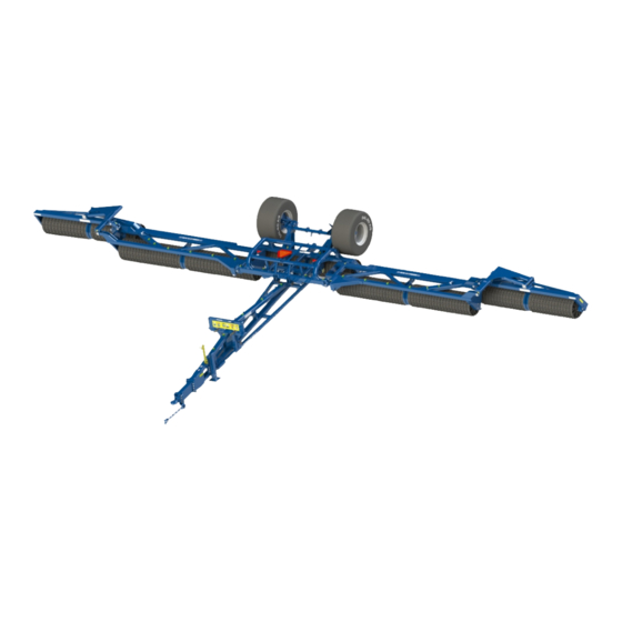
POWERROLL 1430
Manual
DALBO POWERROLL 1430 Manual
Hide thumbs
1
2
3
Table Of Contents
4
5
6
7
8
9
10
11
12
13
14
15
16
17
18
19
20
21
22
23
24
25
26
27
28
29
30
31
32
33
34
page
of
34
Go
/
34
Contents
Table of Contents
Troubleshooting
Bookmarks
Table of Contents
Table of Contents
Safety
General
Hydraulics
Assembly
Maintenance and Repair
Road Transport
Correct Use
Technical Data
How to Use this Manual
Delivery
Uses
Connecting and Disconnecting
Connecting
Hydraulics
Disconnection
Setting up
Adjusting Drawbar Height
Adjusting MID-Section
Operation
Extending and Retracting
Extending
Retract
Adjustment of Hydraulic Weight Transfer
Excessive Pressure
Insufficient Pressure
Operating Speed
Power
Troubleshooting
Maintenance
Lubrication
Adjustment
Adjustment of Rollers
Wheels
Hydraulics
Replacement and Repairs
Hydraulics
Replacing Fold/Extend Cylinder for Side Sections (Inner)
Replacing Gasket Set for Extend/Retract Cylinder
Assembly
Replacing Raise/Lower Cylinder
Replacing Gaskets on Raise/Lower Cylinder
Assembly
Removal/Fitting Wheel
Replacing Wheel Bearings
Removing Roller Axles
Replacing Side Section Axles
Fitting Axles with Roller Rings
Replacing the Centre Axle
Replacing Axles, Bearings or Roller Rings
Crosskill Ring
Scrapping
Spare Parts
Advertisement
Quick Links
Download this manual
POWERROLL
ENG
1430/1530/1630/1830
Serial no.: 100-XXX
Table of
Contents
Previous
Page
Next
Page
1
2
3
4
5
Advertisement
Table of Contents
Need help?
Do you have a question about the POWERROLL 1430 and is the answer not in the manual?
Ask a question
Questions and answers
Related Manuals for DALBO POWERROLL 1430
Farm Equipment DALBO MAXIROLL 1030 Manual
(42 pages)
Farm Equipment DALBO MAXIROLL 950 Manual
(40 pages)
Farm Equipment DALBO POWERROLL 1830 Manual
(34 pages)
Farm Equipment DALBO LEVELFLEX 150 Manual
(26 pages)
Farm Equipment DALBO CULTILIFT 300 Manual
(25 pages)
Farm Equipment DALBO 300 Manual
Front-mounted grubber (25 pages)
Farm Equipment DALBO AXR-H Manual
(50 pages)
Farm Equipment DALBO TRIMAX 520 User Manual
(42 pages)
Farm Equipment DALBO ROLLOMAXIMUM XL Manual
(42 pages)
Farm Equipment DALBO MAXICUT Manual
(30 pages)
Farm Equipment DALBO TRIMAX Plus 300 Manual
(29 pages)
Farm Equipment DALBO MAXIROLL 530 Manual
(39 pages)
Farm Equipment DALBO MAXICUT 920 Manual
(49 pages)
Farm Equipment DALBO MINIMAX 450 User Instructions
(49 pages)
Farm Equipment DALBO MAXIDISC 300 Operator's Manual
(27 pages)
Farm Equipment DALBO MAXIDISC Manual
(38 pages)
This manual is also suitable for:
Powerroll 1530
Powerroll 1630
Powerroll 1830
Table of Contents
Print
Rename the bookmark
Delete bookmark?
Delete from my manuals?
Login
Sign In
OR
Sign in with Facebook
Sign in with Google
Upload manual
Upload from disk
Upload from URL


Need help?
Do you have a question about the POWERROLL 1430 and is the answer not in the manual?
Questions and answers