Table of Contents
Advertisement
Quick Links
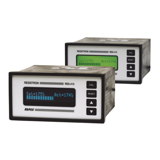
RESISTRON
RES-415
Operating
Instructions
Important features
•
Microprocessor technology
•
LC display (green), 4 lines, 20 characters
Alternatively:
VF display (blue), 4 lines, 20 characters
•
Automatic zero calibration (AUTOCAL)
•
Automatic optimization (AUTOTUNE)
•
Automatic configuration of the secondary voltage and current ranges
(AUTORANGE, as of software revision 100)
•
Automatic frequency adjustment
•
Large current and voltage range
•
Booster connection as standard
•
Reduced menu structure
•
Alarm for „Temperature not OK"
•
Alarm function with fault diagnosis
ROPEX Industrie-Elektronik GmbH
Adolf-Heim-Str. 4
74321 Bietigheim-Bissingen (Germany)
Tel.: +49 (0)7142-7776-0
Fax: +49 (0)7142-7776-211
E-Mail:
info@ropex.de
Internet:
https://ropex.de
Data subject to change
Advertisement
Table of Contents

Related Manuals for Ropex RESISTRON RES-415


Summary of Contents for Ropex RESISTRON RES-415
- Page 1 Large current and voltage range • Booster connection as standard • Reduced menu structure • Alarm for „Temperature not OK“ • Alarm function with fault diagnosis ROPEX Industrie-Elektronik GmbH Tel.: +49 (0)7142-7776-0 E-Mail: info@ropex.de Adolf-Heim-Str. 4 Fax: +49 (0)7142-7776-211 Internet: https://ropex.de 74321 Bietigheim-Bissingen (Germany)
-
Page 2: Table Of Contents
Contents General information ....3 Startup and operation ....20 Copyright . -
Page 3: General Information
The temperature coefficient must be taken from the ROPEX application report and must be set accordingly. The use of incorrect alloys with a too low temperature coefficient and incorrect coding of the ®... -
Page 4: Impulse Transformer
The use of an original ROPEX line filter is mandatory in order to comply with the directives mentioned in section "DECLARATION OF CONFORMITY" on page 6. This device must be installed and connected according to the instructions contained in section "Power supply"... -
Page 5: Disposal
General information Disposal This device is subject to Directive 2012/19/EU concerning the reduction of the increasing amount of waste electrical and electronic equipment and the disposal of such waste in an environmentally sound way. To guarantee proper disposal and / or the recover of reusable material, please take the device to a designated municipal collection point and observe local regulations. - Page 6 We also wish to point out that the transformer which is used must be designed in accordance with VDE 0551/EN 61558 or UL 5058 for safety reasons. July 12, 2020 J. Kühner (CEO) ROPEX Industrie-Elektronik GmbH Adolf-Heim-Str. 4 74321 Bietigheim-Bissingen (Germany) Page 6...
-
Page 7: Application
Application Application ® This RESISTRON temperature controller is an integral part of the "series 400", the outstanding feature of which ® is its microprocessor technology. All RESISTRON temperature controllers are used to control the temperature of heating elements (heatsealing bands, beaded bands, cutting wires, heatsealing blades, solder elements etc.), as required in a variety of heatsealing processes. -
Page 8: Description Of The Controller
Description of the controller the system components, in other words the heatsealing band, the impulse transformer, the wiring, the timing sig- nals and the controller itself, are compatible with one another. We will be pleased to contribute our many years of experience your towards optimizing heatsealing system. -
Page 9: Accessories And Modifications
Designed according to EN 61558 with a one-section bobbin. Optimized for impulse operation with RESISTRON temperature controllers. Specified according to the heatsealing application ( ROPEX Application Report). Communication interface CI-USB-1 Interface for connecting a RESISTRON temperature controller with diagnostic inter- face (DIAG) to the PC (USB port). -
Page 10: Modifications (Mods)
Accessories and modifications Adapter for top hat rail mounting, HS-Adapter-01 ® For mounting the RESISTRON temperature controller RES-415 on a top hat rail (DIN TS35). Allows the controller to be installed in the electrical cabinet, for instance, where it is only accessible to authorized persons. Lockable door TUER-S/K-1 Transparent door (with lock) for mounting on the bezel of the controller. -
Page 11: Technical Data
The temperature range and temperature coefficient settings can be specified in range the ROPEX visualization software ( section 10.10 "Diagnostic interface/visuali- zation software (as of software revision 100)" on page 33): Temperature range: 200°C, 300°C, 400°C or 500°C Temperature coefficient: 400…4000ppm (variable setting range) - Page 12 Technical data Degree of protection Front: IP42 (IP65 with transparent front cover, Art. No. 887000) Back: IP20 (+-0.2) (+-0.2) Installation Installed in front panel cutout with (W x H) 138 x 68 Fastened with clips Weight Approx. 1.0kg (incl. connector plug-in parts) Housing material Black plastic, type Noryl SE1 GFN2 Connecting cable...
-
Page 13: Dimensions/Front Panel Cutout
Dimensions/front panel cutout Dimensions/front panel cutout panel cutout outline dimensions front frame ±0.2 ±0.2 x 68 rubber seal mounting clamp terminal blocks front frame front panel terminal wires DIP-switch to select U , I Version 1 RES-415 Page 13... -
Page 14: Installation
4. Wire the system in accordance with the instructions in section 8.3 "Power supply" on page 16, section 8.6 "Wiring diagram (standard)" on page 19 and the ROPEX Application Report. The information provided in section 8.2 "Installation steps" on page 15 must be heeded additionally. -
Page 15: Installation Steps
Installation Installation steps Use heatseal bands with suitable temperature coefficient Heatseal element push-on with coppered ends connectors Heatsealing band R= f (T) No additional Connect U measuring resistance wires directly to in secondary heatsealing band ends Note circuit number Sufficient wire of turns Twisted cross-section... -
Page 16: Power Supply
Connect core to ground. Use transformers with a one section bobbin. The power, duty cycle and voltage values must be deter- mined individually according to the application ( ROPEX SEC. Application Report and "Accessories" leaflet for impulse transformers). -
Page 17: Line Filter
ROPEX line filters are specially optimized for use in RESISTRON control loops. Providing that they are installed and wired correctly, they guarantee compliance with the EMC limit values. You can find the exact specification of the line filter in the ROPEX Application Report calculated for your particular heatsealing application. - Page 18 Installation 8.5.1 PEX-W4 terminal wires terminal block Snap-on for DIN-rail 35 x 7.5 mm or 35 x 15 mm (DIN EN 50022) 8.5.2 PEX-W5 Mounting on DIN-rail 35 x 7.5 mm or 35 x 15 mm (DIN EN 50022). Page 18 RES-415 Version 1...
-
Page 19: Wiring Diagram (Standard)
Installation Wiring diagram (standard) Line filter LF-xx480 RES-415 LINE ALARM OUTPUT max. 30V/0.2A Contact closed prim. by ALARM (see configuration) Impulse transformer sec. Heat- sealing band (Internnal ground) twisted START (HEAT) No external with 24VDC signal grounding allowed! Current transformer Ground for 24VDC signals. -
Page 20: Startup And Operation
Startup and operation connection Line filter LF-xx480 RES-415 LINE Booster ALARM OUTPUT max. 30V/0.2A Contact closed prim. by ALARM (see configuration) Impulse transformer sec. Heat- sealing band (Internnal ground) twisted START (HEAT) No external with 24VDC signal grounding allowed! Current transformer Ground for 24VDC signals. -
Page 21: Front View Of The Controller
Operator keys Wiring diagram Diagnostic interface (on rear of controller) Nameplate Clips Display Rear view of the controller As of software revision 100: Printed wiring diagram ROPEX SEC. PRIM. (L1) FILTER L1 (L2) 0,4 - 120V AUTO (PE) RANGE 30 - 500A... -
Page 22: Controller Configuration
Set the DIP switches for matching the secondary voltage U and the secondary current I to the correct position for your application. You can find the exact configuration of the DIP switches in the ROPEX Application Report calculated for your particular application. Page 22 RES-415... - Page 23 ROPEX visualization software ( section 10.10 "Diagnostic inter- face/visualization software (as of software revision 100)" on page 33). If the ACTUAL temperature is inside the specified tolerance band when the "START" signal is activated, the tem- perature diagnosis is also activated.
-
Page 24: Heatsealing Band
As of software revision 100, an additional delay time (0..9.9s) can be set in the ROPEX visualization software. The first time the lower tolerance band limit is exceeded, the temperature diagnosis is not activated until the parame- terized delay time has elapsed. - Page 25 Startup and operation An overheated or burned-out heatsealing band must no longer be used because the TCR has been altered irreversibly. 9.4.2 Burning in the heatsealing band If a new heatsealing band has been used, the zero point is first of all calibrated while the band is still cold by acti- vating the "AUTOCAL"...
-
Page 26: Startup Procedure
If the zero has not been calibrated successfully, an erro message indicates error codes 104…106, 211. In this case the controller configuration is incorrect ( section 9.3 "Controller configuration" on page 22 and ROPEX Application Report). Repeat the zero point calibration after the controller has been configured correctly. -
Page 27: Controller Functions
RES-415 "RESET" key clears Alarm RESET "UP" and "DOWN" keys for setpoint selection Press (< 2 sec.): Slow change Hold (> 2 sec.): Fast change ROPEX LC display, 4 lines, multilingual optional: VF display, 4 lines, multilingual 10.2 Display 10.2.1 Power-up message A power-up message appears on the display for approximately 2 seconds when the controller is switched on. -
Page 28: Temperature Setting (Set Point Selection)
If "+" characters appear instead of "*" characters in the corners of the top and bottom lines when the power-up message is displayed, the controller configuration has been changed in the ROPEX visual- ization software ( section 10.10 "Diagnostic interface/visualization software (as of software revision 100)"... -
Page 29: Temperature Indication
Controller functions Changes are accepted immediately even when a heating process is active. The maximum value of the setting range is limited to 300°C. The set point that is selected for the heatsealing temperature must be greater than 40°C. If not, the heat- sealing band will not be heated up when the "START"... -
Page 30: Start" Signal (Heat)
Controller functions 2. If the "START" signal (24VDC or contact) is activated, the AUTOCAL function is not executed. 3. Directly after the controller is powered up, the AUTOCAL function cannot be activated if a fault with error code 101…103, 201…203, 801 or 9xx occurs ( section 10.14 "Fault areas and causes" on page 38). If the con- troller has already operated correctly - a minimum of once - after powering up, the AUTOCAL function cannot be activated with error codes 201…203, 304, 308, 801 or 9xx. -
Page 31: Measuring Impulse Duration
The length of the measuring impulses generated by the controller can be set with this parameter. It may be nec- essary to set a measuring impulse that is longer than the default 1.7ms for certain applications ( ROPEX Appli- cation Report). - Page 32 Controller functions Trouble-free operation of the controller is only guaranteed within the specified input voltage toler- ance range. An external voltage monitor must be connected to prevent defective heatseals as a result of low line voltage. Page 32 RES-415 Version 1...
-
Page 33: Diagnostic Interface/Visualization Software (As Of Software Revision 100)
10.10 Diagnostic interface/visualization software (as of software revision 100) An interface with a 6-pole Western socket is provided for systemdiagnostics and process visualization. This inter- face allows a data connection to be set up to the ROPEX visualization software using the ROPEX communication interface CI-USB-1. -
Page 34: 10.13 Error Messages
38 permits each fault to be cleared quickly and efficiently The error codes described below can also be displayed in the ROPEX visualization software ( section 10.10 "Diagnostic interface/visualization software (as of software revision 100)" on page 33) to facilitate troubleshooting. - Page 35 Controller functions Version 1 RES-415 Page 35...
- Page 36 Controller functions Page 36 RES-415 Version 1...
- Page 37 Controller functions Version 1 RES-415 Page 37...
-
Page 38: 10.14 Fault Areas And Causes
Controller functions 10.14 Fault areas and causes Temperature controller HARDWARE The table below explains the possible fault causes. Fault area Explanation Possible causes Load circuit interrupted after U - Wire break, heatsealing band break - Contacting to heatsealing band defective pickoff point ... - Page 39 Controller functions Fault area Explanation Possible causes - Up to software revision 027: DIP switches 4+5 configured incorrectly (I range) signal incorrect - As of software revision 100: I outside permissible range from 30…500A Turns through PEX-W2/W3 cur- - Check number of turns (two or more turns required for rent transformer incorrect currents <...
-
Page 40: Factory Settings
(as of software revision 106) [X] As of software revision 100 With ROPEX visualization software only. Maintenance The controller requires no special maintenance. Regular inspection and/or tightening of the terminals – including the terminals for the winding connections on the impulse transformer – is recommended. Dust deposits on the con- troller can be removed with dry compressed air. -
Page 41: How To Order
Line filter LF- . . 480 06: Continuous current 6A, 480VAC, Art. No. 885500 35: Continuous current 35A, 480VAC, Art. No. 885506 Impulse transformer See ROPEX Application Report for design and ordering information Communication interface CI-USB-1 Art. No. 885650 For more accessories: "Accessories" leaflet... -
Page 42: Index
Index Index Accessories Impulse heatsealing method Adapter for top hat rail mounting Impulse transformer Alarm output Installation Alarm relay Installation procedure Alloy Installation regulations Ambient temperature Application Application Report Line filter AUTOCAL Line frequency Automatic zero calibration Line voltage AUTOTUNE Maintenance Booster Measurement cable... - Page 43 Index Transformer Transportation View of controller Type of construction Visualization software Undervoltage detection Wiring Wiring diagram Version 1 RES-415 Page 43...
Need help?
Do you have a question about the RESISTRON RES-415 and is the answer not in the manual?
Questions and answers