Table of Contents
Advertisement
Quick Links
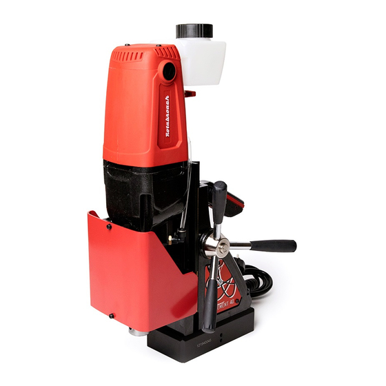
ELEMENT 40 PERM
Magnetic drilling machine
Model number Element40/1PERM & Element40/3PERM
This machine (Serial Number) is CE approved
OSL Cutting Technologies
Burgess Road, Sheffield,
South Yorkshire S9 3WD
United Kingdom
Phone: +44 (0) 114 2212 510
Email: info@rotabroach.co.uk
Fax: +44 (0) 114 2212 563
Website: www.rotabroach.co.uk
Advertisement
Table of Contents

Related Manuals for Rotabroach Element 40 PERM


Summary of Contents for Rotabroach Element 40 PERM
- Page 1 ELEMENT 40 PERM Magnetic drilling machine Model number Element40/1PERM & Element40/3PERM This machine (Serial Number) is CE approved OSL Cutting Technologies Phone: +44 (0) 114 2212 510 Burgess Road, Sheffield, Email: info@rotabroach.co.uk South Yorkshire S9 3WD Fax: +44 (0) 114 2212 563 United Kingdom Website: www.rotabroach.co.uk...
- Page 2 Thank you for purchasing our Element 40 PERM magnetic drill. We would really like your feedback on the machine.
-
Page 3: Table Of Contents
CONTENTS Intended use General safety rules Information Plate Symbols Specification Operational safety procedures Operating instructions Control panel operation Gear selection Extension cable selection Mounting of cutters Capstan operation Remedies for hole making problems Wiring diagram Exploded view of complete machines Exploded view of gearbox and motor units Control panel parts and list Fitting the chuck... -
Page 4: Intended Use
INTENDED USE The intended use of this magnetic drill is to drill holes in ferrous metals. The magnet is used to hold the drill in place whilst the drill is functioning. It is designed for use in fabrication, construction, railways, petrochemical and any other applications when drilling ferrous metal. Any deviation from its intended use will not be covered by warranty. - Page 5 Personal Safety Stay alert, watch what you are doing and use common sense when operating a power tool. Do not use a power tool while you are tired or under the influence of drugs, alcohol or medication. A moment of inattention while operating power tools may result in serious personal injury.
-
Page 6: Information Plate Symbols
INFORMATION PLATE SYMBOLS Refer to the user manual for operational and safety issues with regards to this machine. Dispose of the machine and electrical components correctly. Eye protection must be worn when operating the machine. Ear defenders must be worn when operating the machine. -
Page 7: Specification
SPECIFICATION Maximum hole cutting capacity in .2/.3C steel = 40mm dia. x 50mm deep Arbor bore = 19.05mm (3/4”) dia. Element Element Motor Unit 40/1Perm 40/3Perm Voltages 110V 50-60Hz 230V 50-60Hz Normal Full Load 1200W 210mm long Size 90mm wide Holding Force at 20°C with 25mm minimum plate thickness The use on any material less than 1”m thick will progressively reduce the magnetic performance. -
Page 8: Operational Safety Procedures
OPERATIONAL SAFETY PROCEDURES READ BEFORE USING THE MACHINE • Always take care when lifting and transporting this this machine. The maximum lifting weight for one person is 25kgs. See Fig.1 • When using electrical tools, basic safety precautions should always be followed to reduce the risk of electric shock, fire, and personal injury. -
Page 9: Operating Instructions
(Refer to routine maintenance instructions). • Only use approved cutting fluid do not use water diluted cutting oil. Rotabroach cutting fluid has been specially formulated to maximise the cutters performance. It is available in 1 litre (RD208) and 5 litre (RD229). -
Page 10: Control Panel Operation
CONTROL PANEL OPERATION 1) Magnet ON 2) Motor switch Move the mechanical magnet switch, located on the When the magnet is in the ON position, the GREEN back of the magnet to the ON position. The LED will switch will light up to indicate the motor is ready to start. light up either red of green depending on if sufficient magnetic adhesion has been achieved. -
Page 11: Gear Selection
GEAR SELECTION The Element 40 PERM magnetic drill is fitted with a 2 speed gearbox. The gear is used to reduce the output speed when using larger cutters. Up to 30mm diameter cutters, gear position 1 should be used. -
Page 12: Extension Cable Selection
Should the mains cable become damaged and need replacing, please ensure this is carried out only be an approved Rotabroach Engineer. Assuming a normal AC supply of the correct voltage, it is recommended that the following... -
Page 13: Remedies For Hole Making Problems
REMEDIES FOR HOLE MAKIING PROBLEMS Problems Cause Remedy Attach an additional piece of metal under the magnet, or mechanically Material being cut may be too thin clamp magnetic base to work- for efficient holding. piece. Swarf or dirt under magnet. 1) Magnetic base Clean magnet. - Page 14 REMEDIES FOR HOLE MAKIING PROBLEMS CONT. Problems Cause Remedy Remove cutter, clean part thor- oughly and replace. Always have a new cutter on hand to refer to for correct tooth geome- try, together with instruction sheet. Steel swarf or dirt under cutter. See causes and remedies (2).
-
Page 15: Wiring Diagram
WIRING DIAGRAM Function Wire Colour Mains Neutral Input Blue Motor Neutral Output Black Motor Live Outpur Mains Live Input Brown Function Wire Colour Motor ‘Stop’ Switch 0V White Motor ‘Stop’ Switch +5V White Motor ‘Start’ Switch 0V White Motor ‘Start’ Switch +5V White Magnet ‘ON’... -
Page 16: Exploded View Of Complete Machines
EXPLODED VIEW OF MACHINES... - Page 17 PARTS LIST Item No. Rotabroach P/N Description Qty/Pcs RD43131 Screw M5×16 CSK HD RD45607 M5 CSK Washer RDB3032 Guard Support RDB3118 Slide Channel RDA4201 Screw M4×14 BTTN HD RDC4004 Screw M4×8 BTTN HD RDB3037 Element E40 Guard RDB2034/1(110V) Motor assembly...
- Page 18 Item No. Rotabroach P/N Description Qty/Pcs RDA4204 Screw M3×8 CSK HD RDA4205 M3 Nut RDB3045 Cable chain attachment RDA4206 Screw M4×12 CSK HD RDA5008 Handle insert RD4206 Screw M6×38 CAP HD RD4069 M4 Washer RD4068 M4 nut RD45604 Earth lable...
-
Page 19: Exploded View Of Gearbox And Motor Units
EXPLODED VIEW OF MOTOR AND GEARBOX Item No. Rotabroach P/N Description Qty/Pcs RD4056 Circlip RA354 Button RA3118 Spring RDB3119 Arbor RD4066 Grub Screw M8×8 RDB3020 Arbor spindle RD43304 Oil seal RDA4037 Fluid lever RDB3005 Gear box 8.10 RD45614 Straight Pin 8.11... - Page 20 Item No. Rotabroach P/N Description Qty/Pcs 8.16 RDB4002 Washer 8.17 RDB3049 Helical gear 31T 1.25M 15HA 30PA 8.18 RDB3043 17 tooth gear 8.19 RDB3050 Key steel 4×4×16 8.20 RDB3047 Gear axel 8.21 RM17134 Rolling bearing 608 8.22 RDB2022 Dual gear 8.23...
-
Page 21: Control Panel Parts And List
CONTROL PANEL PARTS AND LIST Item No. Rotabroach P/N Description Qty/Pcs RDA4052 Red Motor Switch RDA4051 Green Motor Switch RDC4093 Green LED RDA4036 Screw M3 X 12 BTTN HD RDB3121 Control Panel Cover RDB3100PERM (110V) Control Plate RDB3101PERM (230V) RDA4019... -
Page 22: Fitting The Chuck
Replacing the chuck is the reverse sequence. MAINTENANCE In order to ‘get the best life’ out of your Rotabroach machine always keep it in good working order. A number of items must always be checked on Rotabroach machines. Always before starting any job make sure the machine is in good working order and that there are no damaged or loose parts. - Page 23 Magnetic base Before every operation the magnetic base should be checked to make sure that the base is flat and there is no damage present. An uneven magnet base will cause the magnet not to hold as efficiently and may cause injury to the operator. Adjustment of slide and bearing bracket alignment.
-
Page 24: Trouble Shooting
TROUBLE SHOOTING - The magnet switch is not connected to the power supply - Damaged or defective wiring - Defective fuse Magnet and motor do not function - Defective magnet switch - Defective control unit - Defective power supply - Damaged or defective wiring - Carbon brushes are stuck or worn out - Defective magnet switch Magnet does function, the... - Page 25 - Damaged or defective wiring - Bottom of magnet not clean and dry - Bottom of magnet not flat - Work piece is not bare metal Insufficient magnetic force - Work piece is not flat - Work piece is too thin less than 3/8” - Defective control unit - Defective magnet - Damaged / defective wiring...
-
Page 26: Cutter Selection, Speeds And Feeds
CUTTING SELECTION AND SPEEDS Material Material Hardness Cutter Mild and free cutting steels <700N/mm² RAP or RAPL Mild and free cutting steels <850N/mm² SRCV or SRCVL Steel angle and joists <700N/mm² RAP or RAPL Steel angle and joists <850N/mm² SRCV or SRCVL Plate and sheet steel <700N/mm²... - Page 27 The data listed below is for reference purpose only, and indicate potential starting conditions. It is the responsibility of the site operation manager to determine correct application requirements. These are only starting points. They will vary with application and work piece condition. Material or Application Type Feed per Tooth (mm) Thin Walled Workpieces...
-
Page 28: Warranty And Ce Statements
90 days, provided that the warranty registration card (or online registration) has been completed and returned to Rotabroach™ or its designated distributor within a period of (30) days from the purchase date. Failure to do so will void the warranty. If the stated is adhered to, Rotabroach™... -
Page 29: Ec Declaration Of Conformity
Based on the referenced test reports, the below product has been found to comply with the relevant harmonised standard(s) to the directive(s) listed on this verification at the time the tests were carried out. Name and address of manufacturer: Rotabroach Ltd Burgess Road, Sheffield Road, Sheffield S9 3WD, United Kingdom Product tested:...
Need help?
Do you have a question about the Element 40 PERM and is the answer not in the manual?
Questions and answers