Table of Contents
Advertisement
Quick Links
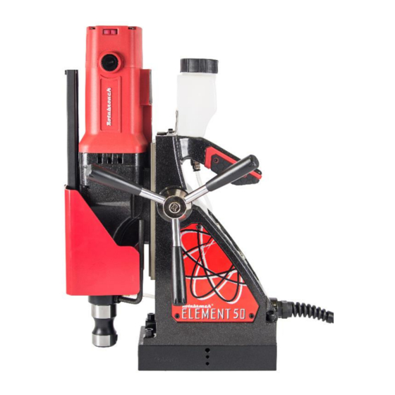
Magnetic drilling & tapping machine
Model Number Element 50/1T, Element 50/3T
This machine (Serial Number ...........................) is CE approved.
Rotabroach Ltd
Burgess Road
Sheffield, South Yorkshire
United Kingdom
S9 3WD
Tel: +44 (0) 114 2212 510
Fax: +44 (0) 114 2212 563
Email: info@rotabroach.co.uk
Website:
www.rotabroach.co.uk
1
Advertisement
Table of Contents

Related Manuals for Rotabroach Element 50/1T


Summary of Contents for Rotabroach Element 50/1T
- Page 1 Magnetic drilling & tapping machine Model Number Element 50/1T, Element 50/3T This machine (Serial Number ......) is CE approved. Rotabroach Ltd Burgess Road Sheffield, South Yorkshire United Kingdom S9 3WD Tel: +44 (0) 114 2212 510 Fax: +44 (0) 114 2212 563 Email: info@rotabroach.co.uk...
- Page 2 Element 50 Manual Original Instructions Aug 2016 Thank you for purchasing our Element 50 magnetic drill. We would really like your feedback on the machine. Other products by Rotabroach: Thank you for your purchase of our product.
-
Page 3: Contents Of The Manual
Element 50 Manual Original Instructions Aug 2016 CONTENTS OF THE MANUAL Page Intended use General safety rules Information plate symbols Specification Operational safety procedures Operating instructions Control panel operation Tapping function Gear selection 10) Magnet detection 11) Extension cable selection 12) Mounting of cutters 13) Capstan operation 14) Remedies for hole making problems... -
Page 4: Intended Use
Element 50 Manual Original Instructions Aug 2016 1) INTENDED USE The intended use of this magnetic drill is to drill holes in ferrous metals. The magnet is used to hold the drill in place whilst the drill is functioning. It is designed for use in fabrication, construction, railways, petrochemical and any other applications when drilling ferrous metal. -
Page 5: Information Plate Symbols
24. The use of any accessory or attachment, other than ones recommended in this instruction manual, may present a risk of personal injury. 25. Have your machine repaired by a qualified Rotabroach technician. This electric tool complies with the relevant safety rules. Qualified persons using original spare parts should only carry out repairs otherwise this may result in considerable danger to the user. -
Page 6: Specification
Height - minimum 446mm Width (including capstan fitting) 195mm Length Overall (including guard) 315mm Nett Weight 15.5kgs 15.2kgs Element 50/1T Element 50/3T Vibration emission value Vibration emission value Vibration total values (triax vector sum) in accordance with ):3.562m/s ):3.527 m/s² EN61029-1: Uncertainty(K):1.5m/s²... -
Page 7: Operational Safety Procedures
Apply a small amount of light oil lubricant regularly to the slide. Cutter breakage is usually caused by insecure anchorage or a loosely fitting slide (Refer to routine maintenance instructions). Only use approved cutting fluid. Rotabroach cutting fluid has been specially formulated to maximise the cutters performance. -
Page 8: Control Panel Operation
Element 50 Manual Original Instructions Aug 2016 7) CONTROL PANEL OPERATION CutSmart™ Technology CutSmart™ Technology Designed for you to get the most out of your machine and your cutters. CutSmart has an easy to read panel that indicates when you are drilling with too much force, which will damage the machine and the cutters. - Page 9 Element 50 Manual Original Instructions Aug 2016 8) TAPPING FUNCTION 1. Ensure power to the machine, red LED will illuminate (1). 2. Press the magnet switch on to engage the magnet. The LED will light up in either green or red (3).
-
Page 10: Gear Selection
Element 50 Manual Original Instructions Aug 2016 9) GEAR SELECTION The Element 50 magnetic drill is fitted with a 2 speed gearbox. The gear is used to reduce the output speed when using larger cutters. Slide Selector Position Speed Controller Setting Level 1 Level 6 200/min... -
Page 11: Mounting Of Cutters
Element 50 Manual Original Instructions Aug 2016 11) EXTENSION CABLE SELECTION The machines are factory fitted with a 3 metre length of cable having three conductors 1.5mm² LIVE, NEUTRAL and EARTH. If it becomes necessary to fit an extension cable from the power source, care must be taken in using a cable of adequate capacity. -
Page 12: Remedies For Hole Making Problems
Element 50 Manual Original Instructions Aug 2016 14) REMEDIES FOR HOLE MAKING PROBLEMS Problem Cause Remedy 1) Magnetic base Material being cut may be too thin for efficient Attach an additional piece of metal under the magnet, or won’t hold holding. -
Page 13: Wiring Diagram
Element 50 Manual Original Instructions Aug 2016 15) WIRING DIAGRAM Function Wire Colour Mains Live Input Brown Speed controller module Lead wire White Speed controller module Lead wire Mains Neutral Input Blue Magnet Positive Output 230V Red,110V Blue Magnet Negative Output Black Field coil Lead wire Blue... - Page 14 Element 50 Manual Original Instructions Aug 2016 Function Wire Colour Motor 'Reverse' Switch 0V White Motor 'Reverse' Switch +5V White Motor 'Forward' Switch 0V White Motor 'Forward' Switch +5V White Magnet Switch 0V White Magnet Switch +5V White Magnet 'ON' LED +5V White + Green Magnet 'ON' LED +5V White + Red...
-
Page 15: Exploded View Of Machine
Element 50 Manual Original Instructions Aug 2016 16) EXPLODED VIEW OF MACHINE... -
Page 16: Parts List
Element 50 Manual Original Instructions Aug 2016 PARTS LIST TS LIST Rotabroach Item# Description Qty/pcs RDC4001 Screw RD45607 M5 CSK Washer RDC4002 Guard support RDC4003 Slide channel RDA4201 Screw M4×14 Button Head RDB3037 Element E40 Guard RDC4004 Screw M4×8 Button Head... - Page 17 Element 50 Manual Original Instructions Aug 2016 Item# Rotabroach P/N Description Qty/pcs RDD4118 Screw M4×12 Button Head RDC4068 Screw RDC4069 Housing RDA5008 Handle insert RD4068 M4 nut RD45604 Earth label RDA4070 Cable clamp RDA4071 Screw M4×22CAP HD RDD4104 Capstan arm...
-
Page 18: Exploded View Of Motor And Gearbox
Element 50 Manual Original Instructions Aug 2016 17) EXPLODED VIEW OF MOTOR AND GEARBOX... - Page 19 Element 50 Manual Original Instructions Aug 2016 PARTS LIST Item# Rotabroach P/N Description Qty/pcs RDC4005 Motor assembly-230V RDC4006 Motor assembly-110V RDC4007 Circlip RDC4008 Oil seal washer RDC4009 Arbor spindle RDC4010 Roll Bearing RDC4011 Flat Key RDC4012 Tapping Screw RDB4008 Spring...
- Page 20 Element 50 Manual Original Instructions Aug 2016 Item# Rotabroach P/N Description Qty/pcs 8.36 RDC4030 Baffle plate 8.37 RDC4031 Tapping Screw RDC4032 Field coil-230V 8.38 RDC4033 Field coil-110V 8.39 RDC4034 Lead wire 8.40 RDC4035 Lead wire 8.41 RDC4036 Motor casing 8.42...
-
Page 21: Control Panel And Parts List
Element 50 Manual Original Instructions Aug 2016 18) CONTROL PANEL AND PARTS LIST Item# Rotabroach P/N Description Qty/pcs RDA4051 Green Motor Switch RDC4090 Blue Motor Switch-Tapping RDC4091 Magnet Switch RDC4092 Red LED RDC4093 Green LED RDA4036 Screw M3×12 BTTN HD... -
Page 22: Fitting Instructions
Element 50 Manual Original Instructions Aug 2016 19) PIPE ADAPTOR KIT RD2311 FITTING INSTRUCTIONS Dependent upon the size of the pipe to be cut (see illustrations) attach adjustable angle plates RD3328 with cap screws RD4325 and washers RD4205 (4 off each) to the magnet sides. Do not tighten. -
Page 23: Fitting The Chuck
Replacing the chuck is the reverse sequence, by utilising RDC4086 (Drift). 21) MAINTENANCE In order to ‘get the best life’ out of your Rotabroach machine always keep it in good working order. A number of items must always be checked on Rotabroach machines. - Page 24 Element 50 Manual Original Instructions Aug 2016 Magnetic base Before every operation the magnetic base should be checked to make sure that the base is flat and there is no damage present. An uneven magnet base will cause the magnet not to hold as efficiently and may cause injury to the operator.
-
Page 25: Troubleshooting
Element 50 Manual Original Instructions Aug 2016 22) TROUBLE SHOOTING 21) MAINTENANCE Magnet and motor do not function - The magnet switch is not connected to the power supply - Damaged or defective wiring - Defective fuse - Defective magnet switch - Defective control unit - Defective power supply Magnet does function, the motor does not... -
Page 26: Cutter Selection And Speeds
Element 50 Manual Original Instructions Aug 2016 23) CUTTER SELECTION AND SPEEDS Material Material Hardness Cutter Mild and free cutting steels <900N/mm² RAP or RAPL Mild and free cutting steels <900N/mm² SRCV or SRCVL Steel angle and joists <900N/mm² RAP or RAPL Steel angle and joists <900N/mm²... -
Page 27: Warranty Statement
Rotabroach™ or its designated distributor within a period of (30) days from the purchase date. Failure to do so will void the warranty. If the stated is adhered to, Rotabroach™ will repair or replace (at its option) without charge any faulty items returned.
Need help?
Do you have a question about the Element 50/1T and is the answer not in the manual?
Questions and answers