Table of Contents
Advertisement
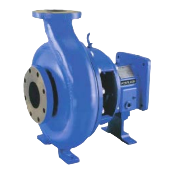
Peerless Pump Company
INSTALLATION, OPERATION,
AND MAINTENANCE MANUAL
ANSI STANDARD PROCESS
CUSTOMER __________________________
PO# _________________________________
SERVICE_____________________________
EQUIPMENT NUMBER__________________
SERIAL NUMBER______________________
Series·8196
Bulletin 4852840
Revised October 9. 2017
PUMP
Advertisement
Table of Contents

Related Manuals for Grundfos Peerless Pump 8196 Series


Summary of Contents for Grundfos Peerless Pump 8196 Series
- Page 1 Peerless Pump Company Series·8196 INSTALLATION, OPERATION, AND MAINTENANCE MANUAL ANSI STANDARD PROCESS PUMP CUSTOMER __________________________ PO# _________________________________ SERVICE_____________________________ EQUIPMENT NUMBER__________________ SERIAL NUMBER______________________ Bulletin 4852840 Revised October 9. 2017...
-
Page 2: Table Of Contents
TABLE OF CONTENTS Section I - General ......................4 Introduction ..........................5 I-A. Importance of Instructions ....................5 I-B. Special Warnings ......................5 I-C. Receiving Inspection-Shortages……………………………………………………..……5 I -D. Preservation and Storage …………………………………………………………..…….5 I-E.· Handling Techniques ………………………………………………………………..…...6 Section II – Installation………………………………………………………………..7 II-A. Location…………………………………………………………………………………..7 II -B. - Page 3 SECTION I Power End Disassembly-STP and MTP Models ...........26 Power End Disassembly-LTP Frames ..............27 Power End Disassembly-XLTP Frames ..............27 V-B. Parts Inspection …………………………………………………………………27-28 V-C. Assembly ......................29 Rotating Element and Bearing Frame, STP and MTP Frames ......29 Power End Assembly ..........
-
Page 4: Section I - General
GENERAL READ THIS ENTIRE BOOK before attempting to install, operate or repair this pump. Properly in- stalled, your pump will give you satisfactory, dependable service. We urge that you carefully read these step-by-step instructions, to eliminate any problems of installation, operation or repair. Failure to read and comply with installation and operating instructions will void the responsibility of the manufacturer and may also result in bodily injury as well as property damage. -
Page 5: Introduction
INTRODUCTION This instruction manual is intended to assist those involved with the installation, operation and maintenance. of Peerless Pump Company ANSI Process Pumps. It is recommended that this manual be thoroughly reviewed prior to installing or performing any work on the pump or motor. I·A. -
Page 6: I-E. Handling Techniques
I-E. HANDLING TECHNIQUES Care should be used in moving pumps. Pumps should not be hoisted by eyebolts. These eyebolts are intended for removing the back pullout assembly for maintenance and inspection. An assembled pump should be hoisted using a sling under suction flange and under rear of bearing frame. Base plate mounted units should be hoisted using slings under suction flange of pump, and frame of motor as shown below. -
Page 7: Section Ii - Installation
SECTION II INSTALLATION II-A. LOCATION Select a location for the pumping unit (pump, base plate, coupling and driver) which will: (a) Be clean, well ventilated, properly drained and provide accessibility for inspection and maintenance (see outline drawing for dimension). Outdoor installations may require protection from the elements, particularly freezing. -
Page 8: Ii-E. Alignment
Adjust the metal supports or wedges until the shafts of the pump and driver are level. Check the coupling faces as well as the suction and discharge flanges of the pump for horizontal or vertical position by means of a level. Correct the positions, if necessary, by adjusting the supports or wedges under the base plate as required. -
Page 9: Ii-F. Alignment Check
Factors that may change the alignment of the pumping unit are: (a) Settling of the foundation (b) Springing of the base plate (c) Piping strains (d) Settling of the building (e) Shift of pump or driver on the base II·F. ALIGNMENT CHECK The following checking procedure applies to a pumping unit consisting of a pump, flexible coupling and driver mounted on a common base plate. -
Page 10: Ii-G. Alignment Adjustment
When significant operating temperature differential will exist between the pump and driver (i.e. steam turbine drive with pump handling cold liquid), thermal growth will cause the hotter unit to rise. Compensate for this growth by initially setting the hotter unit 0.003 inch to 0.005 inch low. When both units are at normal operating temperature, a final check of coupling alignment must be made. - Page 11 When the alignment is correct, the foundation bolts should be tightened evenly, but not too firmly. The unit can then be grouted to the foundation. Foundation bolts should not be fully tightened until the grout is hardened, usually about 48 hours after pouring. Installation without grout completely filling the base plate is acceptable only when recommended by specific notation on the unit outline drawing.
-
Page 12: Ii-J. Suction Piping-General
II-J. SUCTION PIPING-GENERAL The suction piping, if not installed properly, is a potential source of faulty operation. To achieve best performance, provide for the following: (a) Avoid using elbows close to the pump suction flange. A minimum of six pipe diameters of straight pipe should always be located between the elbow and suction inlet. -
Page 13: Ii-L. Engine Driven Units
II-L. ENGINE DRIVEN UNITS Safe and efficient operation of a pumping unit driven by an engine, whether diesel, or gasoline requires the installation to satisfy the following requirements: (a) Be well ventilated to keep the ambient temperature as low as possible. Taking 60 F as a datum point, every 100 F rise in temperature reduces the horsepower of the engine by approximately 1%. -
Page 14: Ii-N. Installation Falk Steelflex® Spacer Couplings
® II·N. INSTALLATION FALK STEELFLEX SPACER COUPLINGS INTRODUCTION - This manual applies to Sizes 20 through 140T31 and 1020 thru 1140T35 Falk Stee1fIex Tapered Grid Spacer Couplings. Unless otherwise stated, information for Sizes 1020 thru 1140 applies to Sizes 20 through 140 respectively, e.g. 1020 = 20, 1100 = 100, etc. The type T31 Steelflex Spacer Assembly permits installation or removal (as shown in Steps A and B below) without disturbing either the driving or driven unit. - Page 15 ® INSTALLATION OF DISASSEMBLED TYPE T31 STEELFLEX COUPLINGS 1. MOUNT SHAFT HUBS· Lockout starting switch of prime mover. Mount shaft hubs on their respective shafts so that hub face is flush fit, with the end of the shaft. If hub is furnished for an interference heat in an-Oil bath as instructed on Page 1.
-
Page 16: Ii-O. Installation Wood's Sure-Flex Spacer Couplings
® II-O. INSTALLATION WOOD'S SURE-FLEX SPACER COUPLINGS Sure-Flex flanges (outer metallic parts) and sleeves (inner elastomeric members) come in many sizes and types. All rubber sleeves (EPDM) and Neoprene) have the same ratings for a given size and may be used interchangeably. Hytrel sleeves, however, has completely different ratings. Rubber sleeves must not be substituted for Hytrel... - Page 17 SURE-FLEX" SPACER COUPLINGS, continued 5. Check parallel alignment by placing a straightedge across the two coupling flanges and. measuring the maximum offset at various points around the periphery of the coupling. 00 NOT rotate the coupling. If the maximum offset exceeds the figure shown under "Parallel" in Table 3, realign the coupling. 6.
-
Page 18: Ii-P. Installation Rexnord Rex Omega® Spacer Type Couplings
II-P. INSTALLATION REXNORD REX OMEGA SPACER TYPE COUPLINGS WARNING • Because of the possible danger to person(s) or property from accidents which may result from improper use or Installation of products, s extremely important to follow the proper installation and operational procedures •... - Page 19 EQUIPMENT ALIGNMENT Although Omega couplings can withstand gross misalignment, care should be taken for best possible alignment to assure optimum performance. The caliper/straightedge alignment procedure is described below. If greater alignment accuracy is desired, a dial indicator method is recommended. There are occasions when equipment manufacturers require more specific alignment tolerances, in which case, the manufacturer's recommendations should be followed.
-
Page 20: Ii-Q. Stuffing Box
II-Q. STUFFING BOX Packing: Stuffing box packing is installed at the factory. Gland bolt nuts should be installed finger tight only. Packing cannot run dry; it must be lubricated. If the pumped liquid is clean, cool fluid, it may be used through a bypass off the discharge to the lantern ring connection to lubricate the packing. -
Page 21: Section Iii - Operation
SECTION III OPERATION III-A START-UP CHECK LIST (a) Checking shaft rotation With power, off and locked out, remove spacer between coupling hubs. Restore power, and momentarily energize motor to determine rotation. Motor shaft must rotate in direction of arrow on the pump bearing frame. Shut off power and lock out. - Page 22 (D) Priming: A centrifugal pump must be primed before it can be operated. If run dry, damage can occur to close- clearance rotating parts and will destroy mechanical seals. If not primed properly, it will not deliver fluid. Prime in one of the following methods: If system has suction pressure, slowly open the suction valve.
- Page 23 After the pump, has been operating for a sufficient length of time to bring it up to operating tem- peratures, the final alignment should be checked. Once the pump has reached operating temperature, stop the pump, lock out the power source, and immediately remove coupling guard. Disconnect coupling and check the alignment.
-
Page 24: Section Iv - Preventive And Corrective Maintenance
SECTION IV PREVENTIVE AND CORRECTIVE MAINTENANCE A planned program of routine inspection and preventive maintenance can increase the service life of your pump. Maintenance records should be kept for each pump in a data base which will be beneficial in developing long term maintenance planning. -
Page 25: Section V - Stp/Mtp Power Frames
SECTION V STP/MTP POWER FRAMES V-A. DISASSEMBLY AND REASSEMBLY INSTRUCTIONS REQUIRED TOOLS WARNING Proper methods to handle pump components must always be used to avoid physical injury or damage to parts. Lock out power supply to motor, dose off suction and discharge valves. Drain liquid from casing and flush if required. -
Page 26: Removal Of Stuffing Box Cover-Packed Pumps
Remove mechanical seal rotary (non-partridge type) from pump shaft sleeve by loosening set screws and sliding assembly off of pump sleeve. (g) Slide shaft sleeve forward and remove from shaft (126). (h) Slide seal gland with stationary seat and O-ring gasket off of pump shaft. REMOVAL OF STUFFING BOX COVER·PACKED PUMPS (i) Remove packing gland studs (353) and nuts (353A). -
Page 27: Power End Disassembly-Ltp Frames
POWER END DISASSEMBLY-LTP FRAMES (a) Remove bearing housing bolts (370C), loosen jam nuts (423). Tighten jack bolts (3700) evenly. Bear- ing housing will begin to back out of frame. (b) Slide shaft assembly, with bearing, housing out of bearing frame. (c) Remove all jack screws and nuts, items (3700) and (423). - Page 28 CASING- Visually inspect for signs of wear, corrosion, or pitting. The casing should be replaced if wear ex- ceeds Ys" deep. Check gasket surface for signs of corrosion or irregularities. IMPELLER- Visually inspect impeller vanes for wear, erosion, or corrosion damage. If vanes are worn more than Ys"...
-
Page 29: V-C. Assembly
SHAFT RUNOUT (WITH SLEEVE) IN INCHES ASSEMBLY (See Isometric View, Pages 53 & 54) ROTATING ELEMENT AND BEARING FRAME, STP AND MTP FRAMES BEARING FRAME - INSPECT TAPPED CONNECTIONS FOR DIRT, CLEAN AND CHASE THREADS AS NECESSARY. USE THREAD SEALANT ON ALL THREADS AND FITTINGS. (a) Install oil fill plug (113A), oil sight glass (143), oil mist/grease plugs (408H), oil cooler inlet and outlet plugs (408L) and (408M). -
Page 30: V-D. Assembly
Apply thin film of lubricant to frame bore I.D. Install shaft assembly into bearing frame (228). Rotate shaft to make sure that it turns freely. Install cap screws (370C), into bearing frame (228). (k) Install jack bolts (370D) and lock nuts (423). Hand tighten evenly. On MTP frames, install new 0-ring gasket in frame face (360D). -
Page 31: Rotating Element-Xltp Frame
ROTATING ELEMENT-XLTP FRAME (a) Install outboard bearing (112) on shaft. (b) Install bearing lock washer (382) on shaft. Place tang of lock washer in shaft keyway. Thread locknut (136) onto shaft. Tighten nut until snug and bend tang of lock washer (382) over flat on nut. If it is necessary to adjust the position of the locknut so that the tang will lineup with the flat, always tighten the nut, never loosen it. -
Page 32: Packed Type Pumps
PACKED TYPE PUMPS (a) Install stuffing box cover (184) with studs and nuts (370H, 423B) Mount dial indicator on end of shaft and check seal chamber cover run out. Rotate shaft a full 360 degrees. Maximum dial indicator reading should not exceed 0.005 on any of the following readings: (1) Outside diameter of the pilot fit. - Page 33 (h) Install mechanical seal stationary into mechanical seal gland, Follow seal manufacturer's (250). instructions. Slide seal gland with stationary seal seat over shaft and position gland back towards the adapter face. Reinstall shaft sleeve. Follow the manufacturer's instructions and install the rotating seal assembly on the shaft sleeve/shaft.
-
Page 34: V-E. Installation-Back Pull Out Assembly - All Models
INSTALLATION-BACK PULL OUT ASSEMBLY -ALL MODELS (a) Inspect casing. Clean casing fit and install gasket (351) onto seal chamber/stuffing cover. Loosen cap screws (390C) and jacking bolts (370D). Install back pull out assembly in casing. (c) Apply anti - seize compound to casing bolts (370). Install casing bolts hand tight. Torque casing bolts to values shown in Appendix. -
Page 35: Appendix
APPENDIX OIL LUBRICATED BEARINGS PUMPS ARE NOT SHIPPED FROM THE FACTORY WITH OIL. RESPONSIBILITY FOR FILL- ING THE BEARING FRAME WITH THE PROPER TYPE AND AMOUNT OF OIL IS THE RESPONSIBILITY OF THE USER. Remove item (113A) oil fill plug and fill frame with oil to the center of the sight glass. If a Trico oiler is used, follow instructions below in Figure A. -
Page 36: Grease Lubricated Bearings
RECOMMENDED OIL MANUFACTURERS GREASE LUBRICATED BEARINGS (a) Clean any dirt or foreign matter from the grease fittings. Remove grease relief plugs from bottom of frame. Pump grease through the fittings and into each bearing cavity until fresh grease comes out of the relief ports. -
Page 37: Field Conversion From Flood Oil To Oil Mist Bearings
FIELD CONVERSION FROM FLOOD OIL TO OIL MIST BEARINGS There are several types of oil mist configurations available from various manufacturers. The following instructions are for conversion of flood oil lubrication to a continuous purge oil mist system. (a) Install oil mist inlet connections (14) inch at top inboard and outboard tapped connections on bearing frame. -
Page 38: Impeller Clearance Adjustment
BEARING IDENTIFICATION MRC - SKF OR EQUAL IMPELLER CLEARANCE ADJUSTMENT If a gradual loss in head and/or capacity occurs, performance may be restored by adjusting the impeller. If performance cannot be restored by adjustment, the pump should be disassembled and impeller and casing inspected for wear. -
Page 39: Dial Indicator Adjustment Of Impeller Clearance
Figure D. (c) Tighten jacking bolts (370D) evenly, until bearing housing backs out and contacts the bearing housing bolts (370C). Tighten jam nuts (423) evenly. Rotate shaft to make sure that it turns freely. (d) Reinstall coupling guard. DIAL INDICATOR ADJUSTMENT OF IMPELLER CLEARANCE LOCK OUT POWER SUPPLY TO MOTOR. - Page 40 (d) Loosen jacking bolts (370D) and jam nuts (423). (e) Tighten bearing housing bolts (370C) evenly, while slowly rotating the shaft until the impeller just starts to rub on the casing. Set dial indicator to zero. Tighten the jacking bolts (370D) evenly, until they contact the bearing frame. Continue to tighten the jacking bolts evenly, about one flat at a time, drawing the bearing housing away from the frame until the dial indicator shows the proper clearance, from .015 inch to .025 inch.
-
Page 41: Parts List With Materials Of Construction
PARTS LIST WITH MATERIALS OF CONSTRUCTION MATERIALS OF CONSTRUCTION MATERIAL CODE SPECIFICATION 316 STAlNLESS STEEL CAST, ASTM A743, GRADE CF-BM 317 STAINLESS STEEL CAST, ASTM A743, GRADE CG-BM ALLOY20 CAST, ASTM A743, GRADE CN-7M CAST IRON ASTM A48, CLASS 30 CAST IRON ASTM A48, CLASS 25 ASTM A743, GRADE CD4MCu... -
Page 42: Stp
STP FRAME Cross Sectional Drawing ITEM# DESCRIPTION ITEM# DESCRIPTION Casing Locknut, Bearing Bolt, Casing Ring, Lantern Plug, Casing Drain 358A Housing; Bearing, Outboard Impeller 370C Bolt, Bearing Housing Jack Bolt, Bearing Housing Shaft 370D Cover, Stuffing Box Jam nut, Bearing Housing Jack Bolt Box Cover/Adapter Stud Retaining Ring, Bearing 370H... -
Page 43: Mtp
MTP FRAME Cross Sectional Drawing ITEM# DESCRIPTION DESCRIPTION ITEM# Casing Plug, Oil Cooler Outlet (Not Shown) 406M Bolt, Casing Plug, Oil Fill 113A Foot, Casing Locknut, Bearing Plug, Casing Drain 358A Ring, Lantern Housing· Bearing, Outboard Bolt Casing Foot Impeller 370C Bolt Bearing Housing Shaft... -
Page 44: Ltp
LTP FRAME Cross Sectional Drawing ITEM# DESCRIPTION ITEM# DESCRIPTION Casing Locknut, Bearing Bolt, Casing Ring, Lantern Foot, Casing Housing; Bearing, Outboard 358A Plug, Casing Drain 370C Bolt, Bearing Housing Bolt, Casing Foot 370D Jack Bolt, Bearing Housing Impeller Jam Nut, Bearing Housing Jack Bolt Shaft 109C Cover;... -
Page 45: Xltp
XLTP FRAME Cross Sectional Drawing ITEM# DESCRIPTION ITEM# DESCRIPTION Ring, Lantern Casing Housing; Bearing, Outboard Bolt, Casing Bolt, Bearing Housing 370C 358A Plug, Casing Drain Jack Bolt, Bearing Housing 370D Impeller Jam Nut, Bearing Housing Jack Bolt Shaft 408H Plug, Bearing Housing Lubrication Cover, Stuffing Box 109C Cover;... -
Page 46: Ansi Process Pumps Engineering Data
ANSI PROCESS PUMPS ENGINEERING DATA PRESSURE/TEMPERATURE RATINGS CONTACT FACTORY FOR SUCTION PRESSURES OVER 160 PSIG. Page 46 4852840... - Page 47 Engineering Data 4852840 Page 47...
-
Page 48: Trouble-Shooting: Causes And Corrective Measures
Pump Trouble-Shooting Common Pump Operational Problems Page 48 4852840... -
Page 49: Ordering Spare Parts
ORDERING SPARE PARTS To insure against possible long and costly downtime periods, especially on critical services, it is advisable to have spare parts on hand. For critical services: It is recommended that a "back pull-out assembly" be kept on hand. This is a group of assembled parts which includes all parts except the casing and the coupling. -
Page 50: Modular Interchangeability Chart
Modular Interchangeability Chart Page 50 4852840... -
Page 51: Stp
STP Exploded Isometric View 4852840 Page 51... -
Page 52: Mtp
MTP Exploded Isometric View Page 52 4852840... -
Page 53: Ltp
LTP Exploded Isometric View 4852840 Page 53... -
Page 54: Xltp
XLTP ·Exploded Isometric View Page 54 4852840...
Need help?
Do you have a question about the Peerless Pump 8196 Series and is the answer not in the manual?
Questions and answers