NAL RESEARCH CORPORATION 9602-LP User Manual
Hide thumbs
Also See for 9602-LP:
- Manual (42 pages) ,
- Quick start manual (3 pages) ,
- Quick start manual (3 pages)

Related Manuals for NAL RESEARCH CORPORATION 9602-LP


Summary of Contents for NAL RESEARCH CORPORATION 9602-LP
- Page 1 451-92750-001A 9602-LP User Guide Version A April 20, 2022 Copyright © 2020 by NAL Research Corporation 11100 Endeavor Ct., Suite 300 Manassas, Virginia 20109 USA Phone: 703-392-1136 Email: contact@nalresearch.com...
- Page 2 EGAL ISCLAIMER AND ONDITION OF This document contains information for the 9602-LP Tracker and accompanying accessories (“Product”), which is provided “as is.” Reasonable effort has been made to make the information in this document reliable and consistent with specifications, test measurements and other information.
- Page 3 9602-LP User Guide Version A EVISION ISTORY Revision Date Description 1.4.6 04/05/2021 Initial version 03/28/2022 Formal release; updated to new template Document Number: 451-92750-001A 3 of 61...
- Page 4 9602-LP User Guide Version A EFERENCE OCUMENTS The latest revisions of the NAL documents are available from the NAL Research website at https://www.nalresearch.com/support/documentation-downloads/. Reference Title Revision/Date Version A, AT Commands for 9602-LP 04/20/2022 Document Number: 451-92750-001A 4 of 61...
-
Page 5: Table Of Contents
9602-LP User Guide Version A ABLE OF ONTENTS Introduction ....................10 Multi-interface Connector ................12 External DC Power Input ................... 13 RS232 Serial Data Interface ................14 2.2.1 Baud Rate ....................15 2.2.2 Serial Port ....................15 TTL/CMOS Inputs/Outputs ................15 Configuration Settings .................. - Page 6 IGURES Figure 1: 9602-LP Mountable Tracker ................. 10 Figure 2: Multi-Interface Connector ................12 Figure 3: Power Input Setting for the 9602-LP ............. 14 Figure 4: Model HRC-24-12 Data/Power Cable Assembly ..........14 Figure 5: Configuration Settings: I/O ................16 Figure 6: Emergency Button ..................
- Page 7 Figure 40: Iridium Dial-Up Data Service ..............54 Figure 41: 9602-LP Mechanical Drawing ..............61 ABLE OF ABLES Table 1: Pin Assignments for the 9602-LP Multi-Interface Connector ....... 12 Table 2: Recommended Iridium Antenna’s Design Specifications ........33 Table 3: Standards Compliance .................. 48 Document Number: 451-92750-001A...
- Page 8 9602-LP User Guide Version A LOSSARY AES ......Advanced Encryption Standard BIS ......Bureau of Industry and Security C/A ......Coarse/Acquisition CE ......Conformité Européenne CEP ......Circular error probability CMOS .....Complementary Metal–Oxide–Semiconductor COCOM ....Coordinating Committee for Multilateral Export Controls DAV ......Data After Voice DC ......Direct Current DGPS ......Differential Global Positioning System...
- Page 9 9602-LP User Guide Version A MSAS .....Multi-functional Satellite Augmentation System NIPRNet ....Non-classified Internet Protocol (IP) Router Network NMEA .....National Marine Electronics Association NOC .......Network Operation Center OFAC ......Office of Foreign Asset Controls PDA ......Personal digital assistant PMS ......PECOS message structure PPP ......Point-to-Point Protocol...
-
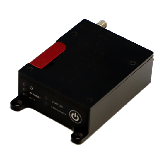
Page 10: Introduction
Figure 1: 9602-LP Mountable Tracker It is self-contained, relying on an extremely low-power consumption microcontroller for operation. The 9602-LP measures 2.73” x 2.17” x 0.94”, weighs less than 5 ounces, and can be attached to high-value, untethered, or non-powered assets such as shipping containers, barges, railcars, trailers, buoys, or even to a person. - Page 11 When a Data Terminal Equipment (DTE) is connected to the 9602-LP with SatTerm software installed (or any terminal emulator software), the DTE can be used to set up the operating parameters of the 9602-LP via a serial connection. A DTE can be a desktop computer, a laptop computer, or a tablet.
-
Page 12: Multi-Interface Connector
ULTI INTERFACE ONNECTOR The multi-interface connector on model 9602-LP is a standard male 15-pin miniature D-Sub type (DB-15) connector, as shown in Figure 1. Figure 2: Multi-Interface Connector The connector comprises four interfaces with the pin assignments shown in Table 1. These interfaces include: ... -
Page 13: External Dc Power Input
Remove the modem’s top plate to find the jumper. With the 9602-LP held in the position shown in Figure 3 (DB15 connector to the left), the 9602-LP is set for 3.6 VDC to +5.3 VDC when the red jumper is on the middle and top pins, ... -
Page 14: Rs232 Serial Data Interface
Figure 3: Power Input Setting for the 9602-LP Important: You can remove the 9602-LP’s top plate to set the jumper but not for repair or services. The warranty is voided, if the 9602-LP is disassembled for any reason other than to set the jumper. -
Page 15: Baud Rate
9602-LP User Guide Version A 2.2.1 The 9602-LP does not support autobaud; the default baud rate is factory set at 19.2 Kbps. The baud rate can be reconfigured with the +IPR command ranging from 4.8 Kbps to 115.2 Kbps. 2.2.2 ERIAL The serial port allows a connected DTE to configure the 9602-LP using NAL Research’s... -
Page 16: Figure 5: Configuration Settings: I/O
Under the default configuration, you can trigger Emergency Tracking at any time with a quick press and release of the Emergency button (momentary switch). Once enabled, holding the emergency button longer than three seconds takes the 9602-LP out of Emergency Tracking. When Emergency Tracking is active, the Emergency LED illuminates. - Page 17 9602-LP User Guide Version A This command specifies the type of emergency switch as either momentary (default) or latching (similar to the toggle switch on the 9601-DGS-LP). The momentary switch type functions as described above. When set to latching, Emergency Tracking is enabled only when the trigger is active.
-
Page 18: Configuration Settings
ONFIGURATION ETTINGS ODES OF PERATION The 9602-LP can be in one of two operating modes when turned on: (1) Command mode, or (2) Tracking mode. 3.1.1 OMMAND When in Command mode, AT commands can be entered to configure the 9602-LP’s operating profiles, or the 9602-LP can be operated as a 9602-G (standard SBD-modem with GPS). -
Page 19: Normal Tracking Mode
ORMAL RACKING Normal Tracking is the mode when the 9602-LP is configured to turn on with the AT^START1 command or after transitioning from Command mode to Tracking mode with the AT^TRK command. Normal Tracking provides a wide range of unique settings, as shown in Figure 8. -
Page 20: Figure 8: Normal Tracking Mode: Settings
TTL/CMOS input signal is detected. Once the last GPS report is sent, the 9602-LP goes back to Normal Tracking. The “Same Place Skip Reports” option prevents GPS reports from being transmitted if the 9602-LP does not move outside a defined radius. -
Page 21: Figure 9: Normal Tracking "Callable (Yes)" Option
The 9602-LP draws the lowest current in between reports of around 60 μA at 5 VDC. The 9602-LP will not respond to any entered commands, including the +++. The +++ command works only while the tracker is waiting for GPS acquisition or is transmitting a report. -
Page 22: Figure 10: Normal Tracking "Callable (No)" Option
When you select the “Callable (No)” option (see Figure 10) and select the Awake on Motion option (see Figure 11), the 9602-LP can be triggered by an internal motion sensor to send a GPS report. The 9602-LP has a built-in motion sensor that works regardless of how the 9602-LP is mounted or aligned. -
Page 23: Figure 11: Normal Tracking "Awake On Motion
After valid motion is detected and a successful GPS report is sent, the 9602-LP goes back to sleep with all circuits OFF. It ignores the motion sensor input signal for Motion Sensor Wait minutes. All other parameters and I/O pins are still observed by the 9602-LP. -
Page 24: Emergency And Test Tracking Modes
Normal Tracking. The Emergency GPS reports have a special data bit activated to alert the recipient of the message type. The 9602-LP allows GPS reports to be saved on its nonvolatile memory when an Iridium satellite is not available. -
Page 25: Encryption Setting
(see Figure 13). Figure 13: Change Encryption Settings: AES-256 Bit Encryption A factory-default Crypto Officer Password is initially set and saved into the 9602-LP. This default password must be changed before any encryption properties can be set or changed. -
Page 26: Miscellaneous Settings
9602-LP is in the field. The <password> entered must be eight characters in length and all printable characters are allowed. The factory-set password is 12345678, and there is no requirement to change this password. -
Page 27: Led Settings
It can be turned off/on again by momentarily holding down and releasing the power button. Using AT command ^IPS, the 9602-LP can also be set to turn on by pressing the power button when DC power is first applied to pin 1 or pine 9. If the device is sleeping in between reporting cycles, pressing the power button turns the 9602-LP on for 10 seconds. -
Page 28: Figure 16. Configuration Settings Window: Led's Option
SBD message is not being acknowledged by the gateway or if a message received from the gateway contains an error(s). The LED blinks only after the 9602-LP is turned on with the last SBD session having an error but the next SBD session is error-free. -
Page 29: Tracking Settings
Start-Up Mode sets the power-up mode of the 9602-LP. The 9602-LP allows GPS reports to be saved on its nonvolatile memory with the Data Log Tracking option turned on. When its memory is full, the oldest reports are overwritten. SatTerm can be used to retrieve all position reports at a later time through the multi-interface serial port. -
Page 30: Figure 17: Configuration Settings Window: Tracking Options
9602-LP User Guide Version A Figure 17: Configuration Settings Window: Tracking Options Document Number: 451-92750-001A 30 of 61... -
Page 31: Gps Settings
From the Configuration Setting window, the GPS option allows you to obtain GPS information from the 9602-LP serial port while the unit is in Command mode or Tracking mode (similar to the command ^PG). Both GPS NMEA formats and updating (streaming) rate can be defined (see Figure 18). -
Page 32: Motion Sensor
OTION ENSOR The 9602-LP has a built-in sensor that can reliably detect motion. It is truly an omnidirectional movement sensor and functions regardless of how the 9602-LP is mounted or aligned. It is sensitive to both tilt (static acceleration) and vibration (dynamic acceleration). -
Page 33: Iridium Antenna Connector
Iridium signal, as shown in Figure 19. The mating SMA male connectors are readily available from many RF hardware vendors/suppliers. Cable and connector losses between the 9602-LP and the antenna are critical and must be kept to less than 2 dB at the operating frequency of 1616 to 1626.5 MHz. - Page 34 9602-LP User Guide Version A Table 2: Recommended Iridium Antenna’s Design Specifications Parameter Value Return Loss (Minimum) 9.5 dB Gain 0.0 dBic (weighted average minimum) VSWR 1.5:1 Minimum ‘Horizon’ Gain –2.0 dBic (82° conic average) Nominal Impedance 50 Ohms Polarization...
-
Page 35: Gps Antenna Connector
NTENNA ONNECTOR The 9602-LP tracker uses a SubMiniature Version A (SMA) female connector for the GPS antenna, as shown in Figure 21. Any active antenna accepting a bias voltage of 3 VDC is appropriate. However, the Low Noise Amplifier (LNA) gain should not exceed 30 dB. NAL Research offers a magnetic mount GPS antenna as well as dual Iridium/GPS antennas for use with the 9602-LP. - Page 36 Never feed external supply voltage into the active GPS antenna. Always use the bias voltage supplied by the 9602-LP via the SMA antenna connector to power an active GPS antenna. Feeding voltage to the GPS antenna other than the provided bias voltage will damage the 9602-LP.
-
Page 37: Power Consumption
OWER ONSUMPTION This section provides insight to the electrical power profile of the 9602-LP; however, does not describe every situation and permutation possible. It should be used as a starting point for continuing your own development design. The actual usage profile can vary for a number of reasons: 1. -
Page 38: Figure 24: Average Current During Standby (3.5 Vdc To 5 Vdc Input)
9602-LP User Guide Version A At standby in command mode, current is measured when all circuits are on. The average current drawn during standby with 3.6 VDC–5 VDC input and 6 VDC–32 VDC are shown in Figure 24 and Figure 25, respectively. -
Page 39: Figure 26: Average Power Consumption During Standby (3.5 Vdc To 32 Vdc Input)
9602-LP User Guide Version A Figure 26 shows the average power consumption by the 9602-LP at standby in command mode for the entire voltage range. Figure 26: Average Power Consumption During Standby (3.5 VDC to 32 VDC Input) In tracking mode, the 9602-LP goes through three different power consumption segments:... -
Page 40: Figure 27: Stages Of Current Drawn: Tracking Mode
Time (Sec.) Figure 27: Stages of Current Drawn: Tracking Mode The average current drawn by the 9602-LP during sleep with 3.6 VDC–5 VDC input is shown in Figure 28. Figure 28: Average Current During Sleep (3.5 VDC to 5 VDC) Input... -
Page 41: Figure 29: Average Current During Sleep (6 Vdc To 32 Vdc Input)
9602-LP User Guide Version A The average current drawn by the 9602-LP during sleep with 6 VDC–32 VDC is shown in Figure 29. Due to limitations of our signal analyzer, current drawn for voltages above 15 VDC in the μA range could not be measured. The dashed line results from curve fitting (cubic spline) of the data. -
Page 42: Figure 30: Average Power Consumption During Sleep (3.5 Vdc To 32 Vdc Input)
Figure 30: Average Power Consumption During Sleep (3.5 VDC to 32 VDC Input) During the GPS acquisition segment, the average current drawn by the 9602-LP with 3.6 VDC–5 VDC input and 6 VDC–32 VDC are shown in Figure 31 and Figure 32, respectively. -
Page 43: Figure 32: Average Current During Gps Acquisition (6 Vdc To 32 Vdc Input)
9602-LP User Guide Version A Figure 32: Average Current During GPS Acquisition (6 VDC to 32 VDC Input) Figure 33 shows the average power consumption by the 9602-LP during GPS acquisition for the entire voltage range. Figure 33: Average Power Consumption During GPS Acquisition (3.5 VDC to... -
Page 44: Figure 34: Average Current During Sbd (3 Vdc To 6 Vdc Input)
9602-LP User Guide Version A During the SBD transmission segment, the average current drawn by the 9602-LP with 3.6 VDC–5 VDC input and 6 VDC–32 VDC are shown in Figure 34 and Figure 35, respectively. Figure 34: Average Current during SBD (3 VDC to 6 VDC Input) -
Page 45: Figure 36: Average Power Consumption During Sbd Transmission
Figure 36: Average Power Consumption During SBD Transmission (3.5 VDC to 32 VDC Input) All the plots above show that the 9602-LP is more efficient (consumes less power) when it operates in the 3.6 VDC to 5.3 VDC input range, especially in between reports. The actual current profiles may vary for a number of reasons;... -
Page 46: List Of Known Issues
9602-LP User Guide Version A IST OF NOWN SSUES None Document Number: 451-92750-001A 46 of 61... -
Page 47: Technical Support
9602-LP User Guide Version A ECHNICAL UPPORT For technical support, please contact us at: Phone: 703-392-1136 Ext. 200 or Email: contact@nalresearch.com Technical documents are also available to download on NAL Research’s website www.nalresearch.com in the Support > Documentation & Downloads section. -
Page 48: Appendix A: Standards Compliance
9602-LP User Guide Version A A: S PPENDIX TANDARDS OMPLIANCE The 9602 transceiver is designed to meet the regulatory requirements for approval for FCC, Canada, and CE, assuming an antenna with a gain of approximately 3 dBi and adequate shielding. The 9602 transceiver is tested to the regulatory and technical certifications shown in Table 3. -
Page 49: Appendix B: Export Compliance
XPORT OMPLIANCE The 9602-LP is controlled by the export laws and regulations of the United States of America (U.S.). It is the policy of NAL Research to fully comply with all U.S. export and economic sanction laws and regulations. The export of NAL Research products, services, hardware, software and technology must be made only in accordance with the laws, regulations and licensing requirements of the U.S. -
Page 50: Appendix C: Iridium Network
9602-LP User Guide Version A C: I PPENDIX RIDIUM ETWORK The Iridium satellite network is owned and operated by Iridium Communications Inc. It was constructed as a constellation of 66 satellites in low-earth orbit, terrestrial gateways, and Iridium Subscriber Units (ISUs). An ISU can either be an Iridium satellite phone or any of the modems. -
Page 51: Iridium Network Data Capabilities
9602-LP User Guide Version A The Iridium network uses a time domain duplex (TDD) method and transmits and receives in an allotted time window within the frame structure. Because the system is TDD, the ISUs transmit and receive in the same frequency band. The access technology is an FDMA/TDMA (frequency division multiple access/time division multiple access) method whereby an ISU is assigned a channel composed of a frequency and time slot in any particular beam. -
Page 52: Dial-Up Data Service
9602-LP User Guide Version A Figure 38: Iridium Network Data Capabilities ERVICE Dial-up data service provides connectivity through the Iridium satellite network to another Iridium modem, to the Public Switched Telephone Network (PSTN), to the Defense Switch Network (DSN), to a remote LAN (e.g., a corporate network), or to an Internet Service Provider (ISP) at a nominal data rate of 2.4 kilobits per second (Kbps). -
Page 53: Figure 39: Pstn Dial-Up Connectivity
9602-LP User Guide Version A an ISP, as shown in Figure 39. The handshaking and protocols are established between the modems independent of the landline. Figure 39: PSTN Dial-Up Connectivity The Iridium dial-up data service functions in much the same way as the PSTN dial-up connectivity. -
Page 54: Direct Internet Connection
9602-LP User Guide Version A Figure 40: Iridium Dial-Up Data Service IRECT NTERNET ONNECTION The Iridium Direct Internet service allows users to connect to the internet via the Iridium gateway without having to sign up with an internet service provider. This service utilizes a dedicated Apollo Server at the Iridium gateway, which provides high-speed connectivity to the internet and optimizes server-to-Iridium modem communications. -
Page 55: Short Burst Data
9602-LP User Guide Version A effective throughput can be achieved depending on content (graphics and images result in lower effective throughput). HORT URST Short Burt Data (SBD) is a simple and efficient bidirectional transport capability used to transfer messages with sizes ranging from zero (a mailbox check) to 1960 bytes. SBD takes advantage of signals within the existing air interface, without using the dedicated traffic channels. -
Page 56: Rudics
9602-LP User Guide Version A RUDICS RUDICS is an enhanced gateway termination and origination capability for circuit-switched data calls across the Iridium satellite network. When an Iridium modem places a call to the RUDICS server located at the Iridium gateway, the RUDICS server connects the call to a predefined IP address, allowing an end-to-end IP connection between the host application and the Iridium modem. -
Page 57: Appendix D: Design Specifications
9602-LP User Guide Version A D: D PPENDIX ESIGN PECIFICATIONS ECHANICAL PECIFICATIONS Dimensions: ............2.73” L x 2.17” W x 0.94” D (69 mm x 55 mm x 24 mm) Weight:............4.8 oz. (136 g) Enclosure: ............Hard anodized aluminum/EMI shielding Waterproof version of the enclosure is available (Model 9602-BTI) Multi-Interface Connector: ........15-Pin D-Sub... -
Page 58: Electrical Specifications
DC power supply. Take into account voltage drop across the power supply cable to ensure adequate current provided to the 9602-LP during SBD sessions. If input voltage does not stay above 3.0 VDC during surge or high current demand, the 9602-LP will reset itself. -
Page 59: Data I/O Specifications
9602-LP User Guide Version A I/O S PECIFICATIONS Short-Burst Data Mobile-Originated: ....340 bytes per message Short-Burst Data Mobile-Terminated: ....270 bytes per message Hardware Interface: .........3-Wire RS232 Software Interface: ..........AT commands ELATED ARDWARE Antennas: ............SYN7391 Series, SAF2040 Series, SAF5340 Series, SAF5350 Series, SAF4070-IG, SAF7352-IG and SAF5270-G AC Power Adapter: ...........LA-3098 (100–240VAC, 47–60Hz input) -
Page 60: Appendix E: Gps Performance Data
One of the limits may be exceeded but not both As long as power is provided to the 9602-LP, the GPS receiver stores ephemeris data in its memory before turning off (sleeping between reports). The ephemeris data are valid up to two hours and can be used in future startup to improve time-to-first-fix. -
Page 61: Appendix F: Mechanical Drawings
9602-LP User Guide Version A F: M PPENDIX ECHANICAL RAWINGS Figure 41: 9602-LP Mechanical Drawing Document Number: TN2021-001-V-A 61 of 61...
Need help?
Do you have a question about the 9602-LP and is the answer not in the manual?
Questions and answers