NAL RESEARCH CORPORATION 9602-LP Manual
Hide thumbs
Also See for 9602-LP:
- User manual (61 pages) ,
- Quick start manual (3 pages) ,
- Quick start manual (3 pages)
Table of Contents
Advertisement
Quick Links
Advertisement
Table of Contents

Related Manuals for NAL RESEARCH CORPORATION 9602-LP


Summary of Contents for NAL RESEARCH CORPORATION 9602-LP
- Page 1 TN2014-001-V1.4.5 GENERAL DESCRIPTION OF MODEL 9602-LP Version 1.4.5 May 30, 2014 Copyright © 2014 by NAL Research Corporation 9385 Discovery Boulevard, Suite 300 Manassas, Virginia 20109 USA Phone: 703-392-1136 x203 E-mail: contact@nalresearch.com...
- Page 2 LEGAL DISCLAIMER AND CONDITIONS OF USE This document contains information for the Iridium 9602-LP Tracker and accompanying accessories (“Product”) is provided “as is.” Reasonable effort has been made to make the information in this document reliable and consistent with specifications, test measurements and other information. However, NAL Research Corporation and its affiliated companies, directors, officers, employees, agents, trustees or consultants (“NAL...
-
Page 3: Table Of Contents
9.0 POWER CONSUMPTION ....................24 10.0 LIST OF KNOWN ISSUES .................... 32 11.0 TECHNICAL SUPPORT ....................33 APPENDIX A: STANDARDS OF COMPLIANCE ................ 35 APPENDIX B: EXPORT COMPLIANCE INFORMATION .............. 36 APPENDIX C: DESCRIPTION OF THE IRIDIUM NETWORK ............37 NAL Research Corporation (TN2014-001-V1.4.5) -
Page 4: Glossary
Right Hand Circular Polarization RUDICS Router-Based Unrestricted Digital Internetworking Connectivity Solution SBAS Satellite Based Augmentation System Short Burst Data Sub-Miniature Version A Short Message Service Time Division Duplex TDMA Time Division Multiple Access VSWR Voltage Standing Wave Ratio NAL Research Corporation (TN2014-001-V1.4.5) -
Page 5: Purpose
When a data terminal equipment (DTE) is connected to the 9602-LP with SatTerm software installed (or any terminal emulator software), the DTE can be used to setup the operating parameters of the 9602-LP via a serial connection. A DTE can be a desktop computer, a laptop computer or a PDA. - Page 6 DC power supply. Users must take into account voltage drop across the power supply cable to ensure adequate current provided to the 9602-LP during SBD sessions. If input voltage does not stay above 3.0VDC during surge or high current demand, the 9602- LP will reset itself.
-
Page 7: Gps Receiver Performance Data
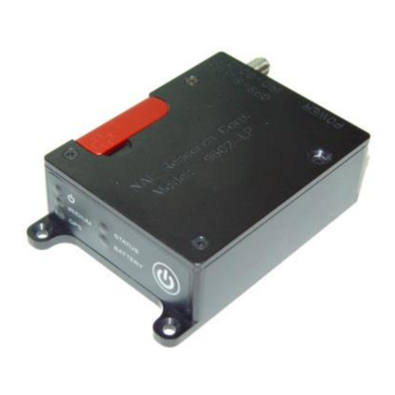
Status LED (Top) Emergency LED Power OFF/ON Button Multi-Interface Connector Iridium Antenna Connector GPS Antenna Connector Figure 1. Iridium Satellite Tracker Model 9602-LP. 3.0 GPS RECEIVER PERFORMANCE DATA Type of GPS Receiver: NEO-6Q from u-blox AG Receiver Type: L1 frequency... -
Page 8: Multi-Interface Connector
One of the limits may be exceeded but not both As long as power is provided to the 9602-LP, the GPS receiver will store ephemeris data in its memory before powering down (sleep between reports). The ephemeris data are valid up to two hours and can be used in future startup to improve time-to-first-fix. - Page 9 THE JUMPER. The jumper can be found by removing the modem’s top plate. With the 9602-LP held in the position shown in Figure 2 (DB15 connector to the left), the 9602-LP is set for 3.6VDC to +5.3VDC when the red jumper is on the middle and top pins and is set for +6.0VDC to +32VDC when the jumper is on the middle and bottom pins.
- Page 10 9602-LP. 4.3 TTL/CMOS Inputs/Outputs The 9602-LP has four TTL/CMOS inputs and three TTL/CMOS outputs. All I/Os are brought out to the multi-interface connector. SatTerm should be used to configure these I/Os as shown in Figure 3 under the I/O tab.
-
Page 11: Configuration Settings
5.0 CONFIGURATION SETTINGS 5.1 Modes of Operation The 9602-LP can be in one of two operating modes at power up: (1) Command mode, or (2) Tracking mode. When in Command mode, AT commands can be entered to configure the 9602-LP’s operating profiles or the 9602-LP can be operated as a 9602-G (standard SBD-modem with GPS). - Page 12 Figure 4. Different Operating Modes of the 9602-LP. Normal Tracking Mode Normal Tracking is the mode when the 9602-LP is configured to power up with AT^START1 command or after transitioning from Command mode to Tracking mode with the AT^TRK command. Normal Tracking offers a wide range of unique settings as shown in Figure 5.
- Page 13 9602-LP’s operating profile to be re-configured remotely in real-time. Since the Iridium RF board is ON at all times, the 9602-LP will consume the most power in between reports (~110mA at 5VDC). The GPS receiver can be left either ON or OFF in between reports to reduce power by ~40mA at 5VDC.
- Page 14 DC converters and serial interfaces. The only active components are the microcontroller and the motion sensor. The 9602-LP will draw the lowest current in between reports of around 60A at 5VDC. The 9602-LP will not respond to any entered commands including the +++. The +++ command will work only while the tracker is waiting for GPS acquisition or is transmitting a report.
- Page 15 When in motion, the sensor produces continuous on-off contact closures (a series of TTL level logic or pulse train) as it chatters open and closed. The signal level is fed directly into the 9602-LP’s micro- controller. When at rest, it normally settles in a closed state.
- Page 16 (Yes)” and “Callable (No)” configurations. When in motion the 9602-LP uses a set of “Callable (Yes)” parameters to send GPS reports and when not in motion the 9602-LP uses a set of “Callable (No)” parameters to send GPS reports. The goal is to allow users the flexibility to define different set of parameters for different operating conditions.
- Page 17 Normal Tracking. The Emergency GPS reports have a special data bit activated to alert the recipient of the message type. The 9602-LP allows GPS reports to be saved on its non-volatile memory when an Iridium satellite is not available.
- Page 18 The Miscellaneous tab offers four settings. “Remote Update Password” sets the required password when a remote update to the current active operating profile is made from a command center while the 9602-LP is in the field. The <password> entered must be 8 characters in length and all printable characters are allowed.
- Page 19 Using AT command ^IPS, the 9602-LP can also be set to power up by pressing the power button when DC power is first applied to pin 1 or pine 9. If the device is sleeping in between reporting cycles, pressing the power button will turn the 9602-LP on for 10 seconds.
- Page 20 Gateway or if a message received from the Gateway contains an error(s). The LED blinks only after the 9602-LP is powered up with the last SBD session having an error but the next SBD session is error-free.
- Page 21 “Remote Message Format” sets format of the messages that will be sent to the command center. “GPS Always ON” forces the GPS receiver to stay on in between reports allowing hot-start each time the 9602-LP wakes up. “Start-Up Mode” sets the power-up mode of the 9602-LP.
-
Page 22: Motion Sensor
The 9602-LP has a built-in sensor that can reliably detect motion. It is truly an omni-directional movement sensor and will function regardless of how the 9602-LP is mounted or aligned. It is sensitive to both tilt (static acceleration) and vibration (dynamic acceleration). The sensor produces a series of TTL level logic or pulse train. -
Page 23: Iridium Antenna Connector
2dB at the operating frequency of 1616 to 1626.5 MHz. NAL Research offers several types of antennas for use with the 9602-LP. These antennas include the fixed mast, mobile magnetic/permanent mount and portable auxiliary. For low-cost and applications where small form-factor and light-weight are required, NAL Research highly recommends model SYN7391-C as shown in Figure 15. -
Page 24: Power Consumption
9.0 POWER CONSUMPTION This section gives users some insight to the electrical power profile of the 9602-LP. It does not describe every situation and permutation possible. It should be used as a starting point for the users to continue their own development design. - Page 25 3.6VDC – 5VDC input and 6VDC – 32VDC are shown in Figures 18 and 19, respectively. 0.20 0.16 0.12 0.08 0.04 0.00 Voltage (DC) Voltage (DC) Figure 18. Average Current during Standby with 3.5VDC to 5VDC Input. NAL Research Corporation (TN2014-001-V1.4.5)
- Page 26 0.04 0.00 Voltage (DC) Voltage (DC) Figure 19. Average Current during Standby with 6VDC to 32VDC Input. Figure 20 shows the average power consumption by the 9602-LP at standby in command mode for the entire voltage range. 1.00 0.75 0.50 0.25...
- Page 27 0.12 0.00 Time History Time (Sec.) The average current drawn by the 9602-LP during sleep with 3.6VDC–5VDC input is shown in Figure 21. Voltage (DC) Voltage (DC) Figure 21. Average Current during Sleep with 3.5VDC to 5VDC Input. NAL Research Corporation (TN2014-001-V1.4.5)
- Page 28 The average current drawn by the 9602-LP during sleep with 6VDC – 32VDC is shown in Figure 22. Due to limitation of our signal analyzer, current drawn for voltages above 15VDC in the A range could not be measured. The dashed line is resulted from curve fitting (cubic spline) of the data.
- Page 29 During the GPS acquisition segment, the average current drawn by the 9602-LP with 3.6VDC – 5VDC input and 6VDC – 32VDC are shown in Figures 24 and 25, respectively. The GPS acquisition time can range from 1 second (hot starts) to 28 seconds (cold starts).
- Page 30 Figure 26 shows the average power consumption by the 9602-LP during GPS acquisition for the entire voltage range. Voltage (DC) Voltage (DC) Figure 26. Average Power Consumption during GPS Acquisition with 3.5VDC to 32VDC Input. NAL Research Corporation (TN2014-001-V1.4.5)
- Page 31 During the SBD transmission segment, the average current drawn by the 9602-LP with 3.6VDC – 5VDC input and 6VDC – 32VDC are shown in Figures 27 and 28, respectively. Voltage (DC) Voltage (DC) Figure 27. Average Current during SBD with 3VDC to 6VDC Input.
-
Page 32: List Of Known Issues
Figure 29. Average Power Consumption during SBD Transmission with 3.5VDC to 32VDC Input. All the plots above show that the 9602-LP is more efficient (consumes less power) when operates in the 3.6VDC to 5.3VDC input range especially in between reports. It should be noted that the actual current profiles may vary for a number of reasons and users are again reminded to optimize their setup to attain the lowest possible power consumption. -
Page 33: Technical Support
11.0 TECHNICAL SUPPORT For technical support, please contact us at: Phone: 703-392-1136 Ext. 200 or E-mail: contact@nalresearch.com Technical documents are also available to download on NAL Research’s website www.nalresearch.com NAL Research Corporation (TN2014-001-V1.4.5) - Page 34 NAL Research Corporation (TN2014-001-V1.4.5)
-
Page 35: Appendix A: Standards Of Compliance
FCC CFR47 Parts 2, EN61000-4-2: 1995/A2: 2001 Part 4.2 15, and 25 EN61000-4-3: 2002 Part 4.3 EN61000-4-4: 2004 EN61000-4-6: 1996/A1: 2001 Part 4.6 EN55022: 2006 Industry Industry Canada Canada RSS170 Issue 1, Rev 1, November 6, 1999 NAL Research Corporation (TN2014-001-V1.4.5) -
Page 36: Appendix B: Export Compliance Information
APPENDIX B: EXPORT COMPLIANCE INFORMATION The 9602-LP is controlled by the export laws and regulations of the United States of America (U.S.). It is the policy of NAL Research to fully comply with all U.S. export and economic sanction laws and regulations. -
Page 37: Appendix C: Description Of The Iridium Network
ISU is assigned a channel composed of a frequency and time slot in any particular beam. Channel assignments may be changed across cell/beam boundaries and is controlled by the satellite. The system will provide an average link margin of 13.1 dB. NAL Research Corporation (TN2014-001-V1.4.5) - Page 38 (SMS) and router-based unrestricted digital internetworking connectivity solution (RUDICS). Dial-up Data (DAV) SMS, SBD Dial-up Data (DAV) Direct Internet AZ, HI or Fucino PSTN RUDICS RUDICS Server Landline SBD, SMS Modem Internet (e-mail) Address Figure D1. Iridium Network Data Capabilities. NAL Research Corporation (TN2014-001-V1.4.5)
- Page 39 The handshaking and protocols established between the modems independent of the Iridium network. For those ISU-to-ISU dial-up calls where data transmission delay is critical such as the application of TCP/IP protocol, DAV should be considered in the design. This option eliminates the Iridium gateway once NAL Research Corporation (TN2014-001-V1.4.5)
- Page 40 , which manages airtime by seamlessly connecting and disconnecting a user through the Iridium system. Airtime charges accumulate only while the call is connected. Improved effective data throughput is achieved through the use of user-transparent data NAL Research Corporation (TN2014-001-V1.4.5)
- Page 41 IP connection between the Host Application and the Iridium modem. There are three key benefits of using RUDICS over the conventional PSTN circuit switched data connectivity or mobile-to-mobile data solutions: (1) elimination of analog modem training time, (2) increased call connection quality, reliability, and maximized throughput and (3) protocol independence. NAL Research Corporation (TN2014-001-V1.4.5)
- Page 42 Geo-location errors in the east-west dimension, therefore, are sometimes more than 100 times greater than in the north-south dimension. NAL Research Corporation (TN2014-001-V1.4.5)
Need help?
Do you have a question about the 9602-LP and is the answer not in the manual?
Questions and answers