
Related Manuals for REPLIGEN XCell ATF6


Summarization of Contents
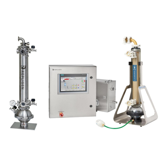
1.0 Description of the XCell™ ATF System and Process
Controller
Dedicated controller for XCell ATF System activity, managing pressure and vacuum.
Filtration Assembly
Assembly of two elements: stainless steel filter housing and silicone diaphragm pump.
A2B Connection Assembly
Tubing assembly connecting Filtration Assembly to bioreactor or process vessel.
Bioreactor Adaptor
Adaptor between Connection Assembly and bioreactor port.
5.0 XCell™ C410v4B Controller Layout
5.1 General Layout
Describes the three main controller components: P-Box, E-Box, and Power-Box.
6.0 C410v4B Controller Process and Control
6.1 Control Overview
Explains the diaphragm pump cycle, driving pressure, and control rules for optimum results.
C. SET UP Section
C.1 BASIC SET UP
Details entries and actions for the basic setup screen.
D. TRENDING Section
D.1 PROCESS TREND
Monitors real-time flow and exhaust set points and process values.
F. ADMIN. Section
F.1 USERS
Details user ID creation, amendment, and security levels.
G. BATCH INFO. Section
G.1 OVERVIEW
Displays current batch information like elapsed time and cycle count.
7.0 XCell™ ATF Hollow Fiber Module and Diaphragm Replacement
7.1 Separating the Filtration Assembly from the bioreactor
Steps to disconnect the Filtration Assembly from the bioreactor.
7.2 HFM removal
Procedure for removing the Hollow Fiber Module from the housing.
8.0 Sterilization
8.1 Preparation of Filtration Assembly for Autoclaving
Steps for preparing the assembly for autoclaving.
9.0 Connection to Bioreactor (ATF-to-Bioreactor)
9.1 Hard Connection
Details the procedure for making a hard connection, including SIP.
10.0 Maintenance
10.1 Diaphragm
Recommendations for diaphragm use and lifespan.
10.2 Pump Air Inlet Filter
Guidelines for replacing the pump air inlet filter.
10.3 “O” Rings, gaskets and Quick Connects
Recommendations for replacing O-rings, gaskets, and quick connects.
Appendix 4: Profinet Communication
Profinet® Infrastructure
Explains the Profinet infrastructure and its components.
Configuration
Lists the factory default IP settings for HMI and PLC.
Appendix 5: Profibus Communication
1.1 Remote Control Mode
How to set the ATF controller to Remote Control Mode.
1.2 Input Signals (from Master to XCell™ ATF)
Describes input signals sent from the Profibus master to the ATF controller.
1.3 Output Signals (to Master from XCell™ ATF)
Describes output signals sent from the ATF controller to the Profibus master.
Black-Box Configuration
How black-box configuration differs from remote control mode.
Prerequisites
Requirements before setting up Profibus communication.
Appendix 6: Delta V Example configuration
1.1 Install the GSD File in Delta V Explorer
Steps to install the GSD file in Delta V Explorer.
Appendix 11: Spare Parts List
XCell™ ATF Electronics Spares
List of spare electronic parts for the XCell ATF system.
XCell™ ATF 6 Pneumatics Spares
List of spare pneumatic parts for XCell ATF 6 system.
Need help?
Do you have a question about the XCell ATF6 and is the answer not in the manual?
Questions and answers