Table of Contents
Advertisement
Quick Links
R718PE01
Wireless Top-Mounted Ultrasonic Level Sensor
Wireless Top-Mounted
Ultrasonic Level Sensor
R718PE01
User Manual
Copyright©Netvox Technology Co., Ltd.
This document contains proprietary technical information which is the property of NETVOX Technology. It shall be
maintained in strict confidence and shall not be disclosed to other parties, in whole or in part, without written
permission of NETVOX Technology. The specifications are subject to change without prior notice.
Advertisement
Table of Contents

Related Manuals for netvox R718PE01


Summary of Contents for netvox R718PE01
- Page 1 User Manual Copyright©Netvox Technology Co., Ltd. This document contains proprietary technical information which is the property of NETVOX Technology. It shall be maintained in strict confidence and shall not be disclosed to other parties, in whole or in part, without written...
-
Page 2: Table Of Contents
5.6 Example for MinTime/MaxTime logic....................... 11 6. Application ................................. 13 7. Installation .................................. 14 8. Comparison between R718PE & R718PE01 ......................16 9. Information about Battery Passivation ........................16 9.1 To determine whether a battery requires activation ................... 16 9.2 How to activate the battery ..........................16... -
Page 3: Introduction
/ material level detection. This device is connected with ultrasonic sensor, which can detect its current liquid level / material level. The detection angle of R718PE01 is about 20 °, which has a stronger transmission signal and is more suitable for the detection of objects such as grain heaps and sand. -
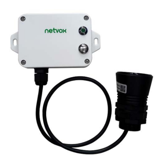
Page 4: Appearance
Low power consumption and long battery life Note: Battery life is determined by the sensor reporting frequency and other variables, please refer to http://www.netvox.com.tw/electric/electric_calc.html. On this website, users can find battery life time for varied models at different configurations. -
Page 5: Set Up Instruction
4. Set up Instruction On/Off Power on Insert batteries. (users may need a screwdriver to open) Turn on Press and hold the function key for 3 seconds till the green indicator flashes once. Turn off (Restore to factory setting) Press and hold the function key for 5 seconds till green indicator flashes 20 times. Power off Remove Batteries. -
Page 6: Data Report
1. The cycle of the device sending the data report is according to the default. 2. The interval between two reports must be the MinTime. Please refer Netvox LoRaWAN Application Command document and Netvox Lora Command Resolver http://www.netvox.com.cn:8888/page/index to resolve uplink data. -
Page 7: Example Of Configurecmd
Device Report Device NetvoxPayLoadData Type Type Battery Status Distance FillLevel Reserved R718PE01 0xB1 0x01 (1Byte, unit:0.1V) (1Byte,0x01_On 0x00_Off) (2Bytes,Unit:1mm) (1Byte,Unit:1%) (3Bytes,fixed 0x00) Ex. Uplink: 01B1012400019014000000 Byte Value Attribute Result Resolution Version DeviceType ReportType Battery 3.6v 24(HEX)=36(DEC),36*0.1v=3.6v Status 6th~7th 0190 Distance... - Page 8 ReadConfig MinTime MaxTime BatteryChange DistanceChange Reserved 0x82 ReportRsp (2bytes Unit:s) (2bytes Unit:s) (1byteUnit:0.1v) (2byte Unit:1mm) (2byte) SetOnDistance OnDistanceThreshold Reserved 0x03 ThresholdRreq (2byte Unit: 1mm) (7Bytes, Fixed 0x00) SetOnDistance Status Reserved 0x83 ThresholdRrsp (0x00_success) (8Bytes, Fixed 0x00) GetOnDistance Reserved 0x04 ThresholdRreq (9Bytes, Fixed 0x00) GetOnDistance OnDistanceThreshold...
-
Page 9: Example Of Switching Mode
(2) Read the device parameter Downlink: 02B1000000000000000000 Device Return: 82B1003C003C0101F40000 (device current parameter) (3) Configure the device parameter FillMaxDistance = 5000mm Downlink: 05B1138800000000000000 Device returns: 85B1000000000000000000 (configuration success) 85B1010000000000000000 (configuration failure) (4) Read device parameter FillMaxDistance Downlink: 06B1000000000000000000 Device returns: 86B1138800000000000000 (device current parameter) 5.3 Example of Switching Mode Switching mode is achieved by setting the values of FillMaxDistance and OnDistanceThreshold. -
Page 10: Example Of Deadzonedistance
If the current device is used as material level detection, switch it to parking space detection (1) Set FillMaxDistance =0 Downlink: 05B1000000000000000000 Device returns: 85B1000000000000000000 (2) Read FillMixDistance, confirm whether it has been set successfully Downlink: 06B1000000000000000000 Device returns: 86B1000000000000000000 (3) Set OnDistanceThreshold= 500mm Downlink: 03B101F400000000000000 Device returns:... -
Page 11: Example Of General Calibration Configuration
5.5 Example of General Calibration Configuration FPort:0x0E Sensor Description PayLoad(Fix =9 Bytes) Type Channel (1Byte) Reserved SetGlobal Multiplier Divisor DeltValue 0x01 0_Channel1 (2Bytes, CalibrateReq (2bytes,Unsigned) (2bytes,Unsigned) (2bytes,Signed) 1_Channel2,etc Fixed 0x00) Channel (1Byte) SetGlobal Status Reserved 0x81 0_Channel1 CalibrateRsp 0x36 (1Byte,0x00_success) (7Bytes,Fixed 0x00) 1_Channel2,etc Distance... -
Page 12: Example For Mintime/Maxtime Logic
(2) Assuming the reported original Distance value is 1000mm, the Calibration is reduced by 100mm,and the reported value is 900mm SetGlobalCalibrateReq:Calibration is reduced by 100mm,Multiplier =0x0001,Divisor = 0x0001,DeltValue = 0xFF9C Downlink: 01360000010001FF9C0000 Device returns: 8136000000000000000000 GetGlobalCalibrateReq: Downlink:0236000000000000000000 Device returns:82360000010001FF9C0000 (3) Clear the calibration value: the reported value is restored to 1000mm ClearGlobalCalibrateReq:... - Page 13 Example#2 based on MinTime = 15 Minutes, MaxTime= 1 Hour, Reportable Change i.e. BatteryVoltageChange= 0.1V MaxTime Sleeping(MinTime) sleeping sleeping sleeping Wakes up and Wakes up and Wakes up and Wakes up and collects data collects data collects data collects data REPORT 3.6V 3.6V 3.6V...
-
Page 14: Application
6. Application In the case of detecting the material level of the barn, the device is installed on the top of the barn, and the device is powered on after fixing. The device collects the distance between the material level and the sensor and the percentage of the material level in the barn at regular intervals. -
Page 15: Installation
7. Installation The actual installation position of the ultrasonic sensor can be installed at the middle position of the top of the container or at the flat position of the top of the container to ensure that the ultrasonic detection direction is perpendicular to the plane of the tested object to ensure the accuracy of measurement. - Page 16 Installation method for reference Open a hole about 45mm on the top of the container of the level to be measured, extend the probe of the lower half of the washer into the hole, and then fix it. The schematic diagram is as follows: Installation precautions 1.
-
Page 17: Comparison Between R718Pe & R718Pe01
The detection angle of R718PE is about 15 °, which is suitable for distance detection in small spaces. The detection angle of R718PE01 is about 20 °, with a stronger transmission signal, which is suitable for the detection of objects such as grain heaps and sand. -
Page 18: Important Maintenance Instruction
10. Important Maintenance Instruction Kindly pay attention to the following in order to achieve the best maintenance of the product: • Do not use or store in dusty or dirty areas. This way can damage its detachable parts and electronic components. •...
Need help?
Do you have a question about the R718PE01 and is the answer not in the manual?
Questions and answers