Table of Contents
Advertisement
Quick Links
R718PE
Wireless Top Mounted Ultrasonic Liquid Level Sensor
Wireless Top Mounted Ultrasonic
Liquid Level Sensor
R718PE User Manual
Copyright©Netvox Technology Co., Ltd.
This document contains proprietary technical information which is the property of NETVOX Technology. It shall be
maintained in strict confidence and shall not be disclosed to other parties, in whole or in part, without written
permission of NETVOX Technology. The specifications are subject to change without prior notice.
Advertisement
Table of Contents

Subscribe to Our Youtube Channel
Related Manuals for netvox R718PE


Summary of Contents for netvox R718PE
- Page 1 R718PE User Manual Copyright©Netvox Technology Co., Ltd. This document contains proprietary technical information which is the property of NETVOX Technology. It shall be maintained in strict confidence and shall not be disclosed to other parties, in whole or in part, without written...
-
Page 2: Table Of Contents
5.6 Example for MinTime/MaxTime logic ................ 13 6. Applications ........................14 7. Installation .......................... 16 8. Comparison between R718PE & R718PE01& R718PE02 ..........19 9. Information about Battery Passivation ................20 9.1 To determine whether a battery requires activation ............20 9.2 How to activate the battery .................. -
Page 3: Introduction
Introduction R718PE is a Class A device based on LoRaWAN open protocol of Netvox. R718PE is a wireless communication device that can detect liquid level and parking space. The device is connected to an ultrasonic sensor to detect its current liquid level or the status of parking space, and the detected data will be transmitted to other devices through the wireless network for display. -
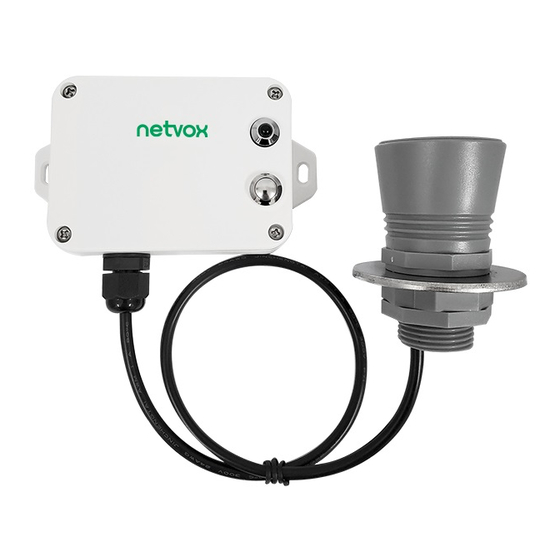
Page 4: Appearance
Appearance Indicator Function Key Ultrasonic Ranging Sensor The distance detected by the sensor is calculated from the plane... -
Page 5: Features
⚫ Low power consumption and long battery life Note: Battery life is determined by the sensor reporting frequency and other variables, please refer to http://www.netvox.com.tw/electric/electric_calc.html. On this website, users can find battery life time for varied models at different configurations. -
Page 6: Set Up Instruction
4. Set up Instruction On/Off Power on Insert batteries. (users may need a screwdriver to open) Turn on Press and hold the function key for 3 seconds until the green indicator flashes once. Turn off (Restore to factory setting) Press and hold the function key for 5 seconds until green indicator flashes 20 times. Power off Remove Batteries. -
Page 7: Data Report
1. The cycle of the device sending the data report is according to the default. 2. The interval between two reports must be the MinTime 3. Please refer Netvox LoRaWAN Application Command document and Netvox Lora Command Resolver http://cmddoc.netvoxcloud.com/cmddoc to resolve uplink data. -
Page 8: Example Of Configurecmd
NetvoxPayLoadData Type Type Battery Status Distance FillLevel Reserved 0x01 (1Byte, (1Byte,0x01_On R718PE 0xB1 (2Bytes,Unit:1mm) (1Byte,Unit:1%) (3Bytes,fixed 0x00) unit:0.1V) 0x00_Off) Example of Uplink: 01B1019F00019014000000 byte (01): Version byte (B1): DeviceType byte (01): ReportType byte (9F): Battery 3.1V (Low Voltage), 9F (HEX) = 31 (DEC), 31* 0.1v = 3.1v... - Page 9 (0x00_success) (8Bytes, Fixed 0x00) GetOnDistance Reserved 0x04 ThresholdRreq (9Bytes, Fixed 0x00) GetOnDistance OnDistanceThreshold Reserved 0x84 ThresholdRrsp (2byte Unit: 1mm) (7Bytes, Fixed 0x00) R718PE 0xB1 SetFillMax FillMaxDistance Reserved 0x05 DistanceReq (2byte Unit: 1mm) (7Bytes, Fixed 0x00) SetFillMax Status Reserved 0x85 DistanceRsp...
- Page 10 (1) Configure the device parameter MinTime = 1min, MaxTime = 1min, BatteryChange = 0.1v, DistanceChange = 500mm Downlink: 01B1003C003C0101F40000 Device Return: 81B1000000000000000000 (configuration success) 81B1010000000000000000 (configuration failure) (2) Read the device parameter Downlink: 02B1000000000000000000 Device Return: 82B1003C003C0101F40000 (device current parameter) (3) Configure the device parameter FillMaxDistance = 5000mm Downlink: 05B1138800000000000000 Device returns:...
-
Page 11: Example Of Switching Mode
5.3 Example of Switching Mode Switching mode is achieved by setting the values of FillMaxDistance and OnDistanceThreshold. If the current device is used as liquid level detection, to switch it to parking space detection, first set FillMaxDistance to 0, and then set OnDistanceThreshold. -
Page 12: Example Of Deadzonedistance
5.4 Example of DeadZoneDistance SetDeadZoneDistance: Downlink: 0BB100FA00000000000000 //set the device detection dead zone distance to 250mm Device returns: 8BB1000000000000000000 GetDeadZoneDistance: Downlink: 0CB1000000000000000000 Device returns: 8CB100FA00000000000000 //set the device detection dead zone distance to 250mm Note: Keep the last set value when restoring the factory setting 5.5 Example of General Calibration Configuration FPort:0x0E Sensor... - Page 13 SensorType = 0x36,channel = 0x00 (The current channel fixed value of the device is 00) (1) Assuming the reported original Distance value is 1000mm, the Calibration is increased by 100mm, and the reported value is 1100mm SetGlobalCalibrateReq:Calibration is increased by 100mm,Multiplier =0x0001,Divisor = 0x0001,DeltValue = 0x0064 Downlink: 0136000001000100640000 Device returns: 8136000000000000000000 GetGlobalCalibrateReq:...
-
Page 14: Example For Mintime/Maxtime Logic
5.6 Example for MinTime/MaxTime logic Example#1 based on MinTime = 1 Hour, MaxTime= 1 Hour, Reportable Change i.e. BatteryVoltageChange=0.1V MaxTime MaxTime leeping(MinTime) leeping(MinTime) Wakes up and collects data Wakes up and collects data Wakes up and collects data REPORTS 3.6V REPORTS 3.5V REPORTS 3.6V Note:... -
Page 15: Applications
Notes : 1) The device only wakes up and performs data sampling according to MinTime Interval. When it is on sleeping mode, it does not collect data. 2) The data collected is compared with the last data reported. If the data variation is greater than the ReportableChange value, the device reports according to MinTime interval. - Page 16 Illustration 1 FillLevel = ((H - D) / H) * 100% Illustration 2 The calculate method of water level percentage of DeadZoneDistance can be set FillLevel = ((H - D) / H-d) * 100% Note: (1) The detecting range of the device is 250mm~8000mm (2) When the device is used as water level detection or trash can detection, the detected distance (Distance) and the percentage of water level or garbage (FillLevel) are reported.
-
Page 17: Installation
(3) When the device is used as parking space detection, it will report the detected distance (Distance) and the parking status (Status) (with car, report “on”; without car, report “off” ), but FillLevel is not reported. (At this time, FillLevel defaults 0.) (4) When Distance ≤... - Page 18 4. If the top of the water tank can be opened, it is recommended to make a hole of diameter 32mm on the top of the water tank. 5. If the top of the water tank cannot be opened, the hole made on the top of the water tank is recommended to be 45mm diameter. It is recommended to add a gasket (size: 32.4*57.4*3mm) between the hole and the sensor.
- Page 19 Sewer If users would like to install the R718PE in a well, the device shall be fixed far from the ladder. The sensor should be vertical to the water surface and horizontal to the wall of the well. It should be installed 25 to 30 cm away from the wall of the well and less...
-
Page 20: Comparison Between R718Pe & R718Pe01& R718Pe02
Note: If the device is used for horizontal measurements, it should be installed ≥ 30 cm away from the floor. (The distance could be > 30 cm if the floor is uneven.) 8. Comparison between R718PE & R718PE01& R718PE02 Model... -
Page 21: Information About Battery Passivation
9. Information about Battery Passivation Many Netvox devices are powered by 3.6V ER14505 Li-SOCl2 (lithium-thionyl chloride) batteries that offer many advantages including low self-discharge rate and high energy density. However, primary lithium batteries like Li-SOCl2 batteries will form a passivation layer as a reaction between the lithium anode and thionyl chloride if they are in storage for a long time or if the storage temperature is too high. -
Page 22: Important Maintenance Instruction
10. Important Maintenance Instruction Kindly pay attention to the following in order to achieve the best maintenance of the product: • Keep the device dry. Rain, moisture, and various liquids or water may contain minerals that can corrode electronic circuits. In case the device is wet, please dry it completely.
Need help?
Do you have a question about the R718PE and is the answer not in the manual?
Questions and answers