Table of Contents
Advertisement
Quick Links
Advertisement
Table of Contents

Related Manuals for SMAR TP300 Series


Summary of Contents for SMAR TP300 Series
- Page 3 In order too be user friendly the function block concept was introduced (users of Smar CD600 should be familiar with this, since it was implemented several years ago). The user may now easily build and overview complex control strategies. Another advantage is adding flexibility, the control system may be edited without having to rewire or change the hardware.
- Page 4 Smar provides specific training to instruct and qualify such professionals. However, each country must comply with the local safety procedures,...
-
Page 5: Table Of Contents
Table of Contents TABLE OF CONTENTS SECTION 1 - INSTALLATION ................................1.1 GENERAL ...................................... 1.1 MOUNTING ....................................1.1 ELECTRONIC HOUSING ROTATION ............................1.7 ELECTRIC WIRING ..................................1.7 BUS TOPOLOGY AND NETWORK CONFIGURATION ........................ 1.8 JUMPER CONFIGURATION ............................... 1.10 POWER SUPPLY ..................................1.10 RECOMMENDATIONS FOR MOUNTING APPROVED EQUIPMENTS WITH THE IP66/68 W CERTIFICATIONS (“W"... - Page 6 TP302 – Operation, Maintenance and Instructions Manual Installation Flowchart Start Has the transmitter been configured Field Installation. in bench for the application ? Verify area classification and its respective practices. Configure the transmitter ( Section 1 and Section 3). Install the transmitter according to the application.
-
Page 7: Section 1 - Installation
Section 1 INSTALLATION General NOTE The installation carried out in hazardous areas should follow the recommendations of Appendix The overall accuracy of measurement and control depends on several variables. Although the converter has an outstanding performance, proper installation is essential, in order to maximize its performance. - Page 8 TP302 – Operation, Maintenance, and Instructions Manual The following Figures 1.1 and 1.3 show both linear and rotary typical mounting: Rotary Movement Install the magnet on the valve stem using the magnet mounting bracket. ROTATY POSITIONER ROTARY POSITIONER MAGNET TRANSMITTER TRANSMITTER BRACKET MAGNET...
- Page 9 Installation Linear Movement Install the magnet on the valve stem using the magnet mounting bracket. The linear magnet movement must be orthogonal in relation to the main axis of the position transmitter. For example, if the linear magnet movement is vertical, the transmitter main axis must be horizontal, as show in Figure 1.3.
- Page 10 TP302 – Operation, Maintenance, and Instructions Manual “L” BRACKET WITH “U” CLAMP FOR REMOTE SENSOR LINEAR MAGNET BRACKET REMOTE POSITION TRANSMITTER VALVE YOKE M6x1 SCREWS VALVE (2 PLACES) STEM LINEAR M6 x 1 SCREWS MAGNET (2 PLACES) CENTRALIZER DEVICE “L” BRACKET WITH “U” CLAMP FOR REMOTE REMOTE POSITION TRANSMITTER...
- Page 11 Installation See below the TP302 and magnets dimensional drawings. Figure 1.5 – TP302 Dimensional Drawing / Magnets Dimensional Drawing...
- Page 12 TP302 – Operation, Maintenance, and Instructions Manual REMOTE SENSOR Leave, at least, a 150 mm space, for THREADS FOR SCREWS zero and span adjustment with the (4.45) 49.5 PLUG M6 x 1 ( 2 PLACES ) magnetic tool. (1.95) (0.35) ELECTRICAL CONNECTION (2.99)
-
Page 13: Electronic Housing Rotation
Installation Electronic Housing Rotation The electronic housing rotates for a better digital display reading. To rotate it, release the housing rotation screw. Figure 1.6 – Cover Locking and Housing Rotation Set Screw Figure 1.7 - Cover Locking Screw Electric Wiring Access the wiring block by removing the electrical connection cover. -
Page 14: Bus Topology And Network Configuration
TP302 – Operation, Maintenance, and Instructions Manual Figure 1.8 – Wiring Block The TP302 uses the 31.25 kbit/s voltage mode option for the physical signaling. All other devices on the same bus must use the same signaling. All devices are connected in parallel along the same pair of wires. - Page 15 Installation Figure 1.9 - Bus Topology Figure 1.10 - Tree Topology...
-
Page 16: Jumper Configuration
The instrument modification or replacement parts supplied by other than authorized representative of Smar is prohibited and will void the certification. Rotary and Linear Magnet The Figure 1.12 shows typical shapes for both magnets. For better transmitter performance, the linear magnet is presented with different lengths. -
Page 17: Remote Position Sensor
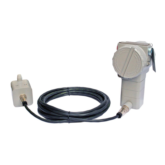
(maximum limit 20 (meters) length), keep it away from possible sources of induction and/or magnetic interference. The cable supplied by Smar is shielded with excellent protection against electromagnetic interference, but despite of this protection, it is recommended to avoid the cable sharing the same conduit with other cables. -
Page 18: Installation In Hazardous Areas
TP302 – Operation, Maintenance, and Instructions Manual Installation in Hazardous Areas Consult the Appendix A for Hazardous Location Approvals. 1.12... -
Page 19: Section 2 - Operation
Section 2 OPERATION Functional Description – Hall Sensor Sensor hall supplies an output voltage proportional to the applied magnetic field. This magnetic sensor is ideal for use in system of sensor of linear or rotary position. The mechanical vibrations do not affect sensor hall. - Page 20 TP302 – Operation and Maintenance Instruction Manual Display Controller Receives data from the CPU identifying which segments on the local indicator use to turn on. The controller drives the backplane and the segment control signals. Local Adjustment There are two switches that are magnetically activated. The magnetic tool without mechanical or electrical contact can activate them.
-
Page 21: Section 3 - Configuration
Section 3 CONFIGURATION One of the many advantages of Fieldbus is that device configuration is independent of the configurator. The TP302 may be configured by a third-party terminal or operator console. The TP302 contains one input transducer block, one resource block, one display block and function blocks. -
Page 22: Parameters Table
TP302 – Operation, Maintenance and Instructions Manual Supported Modes OOS and AUTO. BLOCK_ERR The BLOCK_ERR of the transducer block will reflect the following causes: Input Failure – When mechanic module is disconnected from main electronic board. Out of Service – When the block is in OOS mode. Primary_Value Status The PRIMARY_VALUE status of the transducer block will reflect the following causes: Bad::SensorFailure:NotLimited –... -
Page 23: Calibration
Configuration Data Valid Initial/ Parameter Units Store Description Type Range Default Value The location of last sensor calibration. SENSOR_CAL_LOC VisibleString NULL None This describes the physical location at which the calibration was performed. SENSOR_CAL_DATE Time of Day None The date of the last sensor calibration. The name of person who is in charge SENSOR_CAL_WHO VisibleString... -
Page 24: Position Trim
If a mismatch is detected, a trim can be done. There are at least two ways of doing the trim: using local adjustment or using Syscon (the System Configurator from Smar). When doing the trim, make sure you are using an appropriate meter (with the necessary accuracy). -
Page 25: Via Local Adjustment
Configuration Figure 3.2 - Position Trim – Upper Value WARNING It is recommendable that a convenient engineering unit be chosen by means of parameter XD_SCALE of the Analog Input Block, considering that the range limits of the sensor must be respected, these being 100% and It is also recommendable, for every new calibration, to save existing trim data in parameters CAL_POINT_LO_BACKUP and CAL_POINT_HI_BACKUP, by means of parameter BACKUP_RESTORE, using option LAST_TRIM_BACKUP. -
Page 26: Display Transducer Block
All Series 302 field devices from Smar have the same methodology to handle with it. Therefore, since the user has learned once, he is capable to handle all kind of field devices from Smar. - Page 27 Configuration Inc_Dec It is the increment and decrement in decimal units when the parameter is Float or Float Status time, or integer, when the parameter is in whole units. Decimal_Point_Number This is the number of digits after the decimal point (0 to 3 decimal digits). Access The access allows the user to read, in the case of the “Monitoring”...
- Page 28 TP302 – Operation, Maintenance and Instructions Manual Figure 3.4 - Parameters for Local Adjustment Configuration Figure 3.5 - Parameters for Local Adjustment Configuration...
- Page 29 Configuration Figure 3.6 - Parameters for Local Adjustment Configuration Figure 3.7 - Parameters for Local Adjustment Configuration...
-
Page 30: Programming Using Local Adjustment
TP302 – Operation, Maintenance and Instructions Manual Programming using Local Adjustment The TP302 has two holes for magnetic switches activated by the magnetic tool located under the identification plate. These magnetic switches are activated by one magnetic tool. This magnetic tool enables adjustment of the most important parameters of the blocks. It also enables pre-configuration of the communication. - Page 31 Configuration In this option the Place the magnetic tool in first variable orifice Z. In case this is (P_VAL) is showed the first configuration, the with its respective option shown on the value (if you to display does the want that it keeps configuration tool static, put the tool configure that the tag with...
-
Page 32: Block Type Availability And Initial Block Set
Block Type Availability and Initial Block Set The table below shows how powerful and flexible the Smar devices are. For example, the user may instantiate up to 20 blocks selected from 17 block types (algorithms) in a field device as TP302. -
Page 33: Table Of Points - Linearization
Configuration Table of Points - Linearization The output signal follows a curve determined by 16 points freely configurable. TABLE OF POINTS - LINEARIZATION Actual Value Desired position Points (process Out) value (of the X(%) process ) Y(%) 26.4 5 Points 48.6 (See figure: Position graphic of the magnet) - Page 34 TP302 – Operation, Maintenance and Instructions Manual 3.14...
-
Page 35: Section 4 - Maintenance Procedures
In general, it is recommended that end users do not try to repair printed circuit boards. Spare circuit boards may be ordered from Smar whenever necessary. Refer to the item "Returning Materials" at the end of this section. -
Page 36: Disassembly Procedure
TP302 – Operation, Maintenance, and Instructions Manual SYMPTOM PROBABLE SOURCE OF PROBLEM Noise, Oscillation Adjust damping. Check grounding of the transmitters housing. Check that the shielding of the wires between transmitter / panel is grounded only in one end. Sensor Check the sensor operation;... -
Page 37: Reassembly Procedure
Maintenance Procedures Figure 4.1 - Transducer Rotation Loosen the two screws (3) that anchor the indicator and the main circuit board. Gently pull out the indicator, and then the main board (5). Reassembly Procedure WARNING Do not assemble the main board with power on. Transducer Mount the transducer to the housing turning clockwise until it stops. -
Page 38: Upgrading Tp301 To Tp302
TP302 – Operation, Maintenance, and Instructions Manual Upgrading TP301 to TP302 The sensor and casing of the TP301 is the same as the TP302. By changing the circuit board of the TP301 it becomes a TP302. The display on TP301 version 1.XX, is the same as on TP302 and can therefore be used with the TP302 upgrade circuit board. -
Page 39: Exploded View
Maintenance Procedures Exploded View Figure 4.3 – TP302 Exploded View... -
Page 40: Spare Parts List
TP302 – Operation, Maintenance, and Instructions Manual Spare Parts List SPARE PARTS LIST CATEGORY DESCRIPTION OF PARTS POSITION CODE (NOTE 1) . Aluminum 204-0103 COVER WITH WINDOW . 316 SS 204-0106 COVER O-RING (NOTE 3) . Buna-N 204-0122 . Units with indicator 304-0118 ALUMINUM HOUSING MAIN BOARD SCREW . - Page 41 316 SST Housing (IP/Type) Aluminum for saline atmosphere (IPW/TYPE X) Copper Free Aluminium (IPW/TYPEX) COD. Painting Gray Munsell N 6.5 Polyester Black Polyester Without Painting Safety Blue Epoxy – Electrostatic Painting COD. Manufacturing Standard Smar 400-1314 TYPICAL MODEL NUMBER * Select item.
- Page 42 TP302 – Operation, Maintenance, and Instructions Manual...
-
Page 43: Section 5 - Technical Characteristics
Section 5 TECHNICAL CHARACTERISTICS Functional Specifications Linear Motion: 3 -100 mm; Travel Rotary Motion: 30 - 120º rotation angle. Output Signal Digital only. Fieldbus, 31.25 kbit/s voltage mode with bus power. Bus power: 9 - 32 Vdc. Current consumption quiescent: 12 mA. Output impedance (from 7.8 KHz –... -
Page 44: Ordering Code
TP302 - Manual de Instruções, Operação e Manutenção Ordering Code MODEL POSITION TRANSMITTER FOUNDATION™ fieldbus TP302 COD. Local Display Without Local Display With Local Display COD. Mounting Bracket Without Bracket Carbon Steel, "L" + clamp "U" pipe 2". (3) Stainless Steel, "L" + clamp "U" pipe 2". (3) Carbon Steel, rotary - VDI / VDE NAMUR Stainless Steel, rotary - VDI / VDE NAMUR Carbon Steel, "L"... -
Page 45: Appendix A - Certifications Information
Consult www.Smar.com for the EC declarations of conformity and certificates. Authorized representative/importer located within the Community: Smar Europe BV De Oude Wereld 116 2408 TM Alphen aan den Rijn Netherlands ATEX Directive 2014/34//EU - "Equipment for explosive atmospheres” The EC-Type Examination Certificate is released by DNV GL Presafe AS (CE2460) and DEKRA Testing and Certification GmbH (CE0158). -
Page 46: Hazardous Locations Approvals
TP302 – Certifications Information Instrinsic Safety / Non Incendive application In hazardous areas with intrinsic safety or non-incendive requirements, the circuit entity parameters and applicable installation procedures must be observed. The instrument must be connected to a proper intrinsic safefy barrier. Check the intrinsically safe parameters involving the barrier and equipment including the cable and connections. - Page 47 Appendix A IECEx DNV GL Presafe A/S Explosion Proof (IECEx PRE 21.0015X) Ex db IIC T6 Gb Ta -20 ºC to +60 ºC Options: IP66/68W or IP66/68 Special Conditions for Safe Use ATEX and IECEx certified cable gland to be used. Repairs of the flameproof joints must be made in compliance with the structural specifications provided by the manufacturer.
- Page 48 TP302 – Certifications Information Prova de Explosão (CEPEL 01.0016) CEPEL 01.0016 Ex db IIC T6 Gb Ex tb IIIC T85 ºC Db IP66W/IP68W IP66/IP68 (aço inox e alumínio Copper Free) (alumínio) Observações: A validade deste Certificado de Conformidade está atrelada à realização das avaliações de manutenção e tratamento de possíveis não conformidades, de acordo com as orientações do Cepel, previstas no Regulamento de Avaliação da Conformidade.
-
Page 49: Identification Plates
Appendix A Identification Plates FM Approvals DNV GL Presafe AS / DEKRA Testing and Certification GmbH... - Page 50 TP302 – Certifications Information CEPEL (Centro de Pesquisa de Energia Elétrica)
- Page 51 Appendix A FM Approvals...
- Page 52 TP302 – Certifications Information...
-
Page 53: Appendix B - Srf - Service Request Form
Company: _____________________________________________________________________________________________________ Contact: ______________________________________________________________________________________________________ Title: _________________________________________________________________________________________________________ Section: ______________________________________________________________________________________________________ Phone: _________ _________________________ _________ _________________________ Extension: ____________________ E-mail: ________________________________________________________________________ Date: _______/ _______/ _________ For warranty or non-warranty repair, please contact your representative. Further information about address and contacts can be found on www.smar.com/contactus.asp. -
Page 54: Returning Materials
TP302 - Manual de Instruções, Operação e Manutenção Returning Materials Should it become necessary to return the transmitter and/or configurator to SMAR, simply contact our office, informing the defective instrument serial number, and return it to our factory. In order to speed up analysis and solution of the problem, the defective item should be returned with a description of the failure observed, with as much details as possible.
Need help?
Do you have a question about the TP300 Series and is the answer not in the manual?
Questions and answers