Table of Contents
Advertisement
Quick Links
Advertisement
Table of Contents

Related Manuals for SMAR TP303


Summary of Contents for SMAR TP303
- Page 1 Profibus Simatic www.esma-rt.ru...
- Page 2 Specifications and information are subject to change without notice. Up-to-date address information is available on our website. web: www.esma-rt.ru...
- Page 3 In order too be user friendly the function block concept was introduced. The TP303, like the rest of the 303 family, has some Function Blocks built in, like Analog Input and Totalizer Block. The need for implementation of Fieldbus in small as well as large systems was considered when developing the entire 303 line of Profibus-PA devices.
- Page 4 Smar provides specific training to instruct and qualify such professionals. However, each country must comply with the local safety procedures,...
-
Page 5: Table Of Contents
UPGRADING TP301 TO TP303 ..............................4.3 SECTION 5 - TECHNICAL CHARACTERISTICS ..................5.1 FUNCTIONAL SPECIFICATIONS ..............................5.1 PERFORMANCE SPECIFICATIONS............................5.1 PHYSICAL SPECIFICATIONS..............................5.2 ORDERING CODE..................................5.2 APPENDIX A – SRF – SERVICE REQUEST FORM................A.1 RETURNING MATERIALS................................. A.2 APPENDIX B – SMAR WARRANTY CERTIFICATE ................B.1... - Page 6 TP303 - Operation, Maintenance and Instructions Manual...
- Page 7 Table of Contents Installation Flowchart Quick Installation Guide Start Has the transmitter been configured Field Installation. in bench for the application ? Install the transmitter in protected areas. Configure the transmitter ( section 1 and section 3). Verify area classification and its respective practices.
- Page 8 TP303 - Operation, Maintenance and Instructions Manual VIII...
-
Page 9: Section 1 - Installation
General MOUNTING The mounting of transmitter TP303 will depend on type movement, if it is linear or rotary. Two supports are required for mounting, one for the magnet and the other for the transmitter itself. Smar may supply then both since they are specified in the order code (See page 4.7) Rotary Movement Install the magnet on the valve stem using the magnet support (See figure 1.2). - Page 10 TP303 - Operation, Maintenance and Instructions Manual NOTE Make sure that arrow engraved on the magnet coincides with the arrow engraved on the position transmitter when the system is in mid travel. The magnet mounting in relation to the hall sensor: 1 .
- Page 11 Installation Figure 1.1 – TP303 and Magnet Dimensional Drawing...
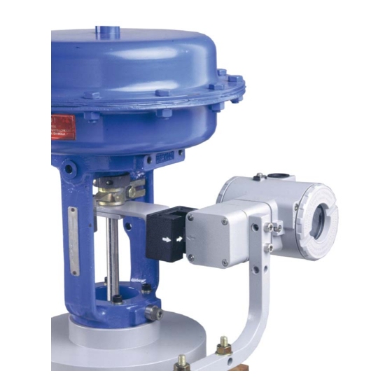
- Page 12 TP303 - Operation, Maintenance and Instructions Manual Figure 1.2 – Transmitter on the Rotary Actuator Figure 1.3 – Transmitter on the Linear Actuator...
-
Page 13: Housing Rotation
Figure 1.5 – Wiring Block The TP303 uses the 31.25 kbit/s voltage mode option for the physical signaling. All other devices on the same bus must use the same signaling. All devices are connected in parallel along the same pair of wires. -
Page 14: Bus Topology And Network Configuration
TP303 - Operation, Maintenance and Instructions Manual WARNING HAZARDOUS AREAS In hazardous zones with explosion proof requirements the covers must be tightened with at least 7 turns. In order to avoid moisture or corrosive gases, hand tighten the covers until the O-rings are compressed. Lock the covers closed with the locking screw. -
Page 15: Intrinsic Safety Barrier
DP/PA coupler, when it is Non-Ex type. Use of DF47 is recommended. Jumper Configuration In order to work properly, the jumpers J1 and W1 located in the TP303 main board must be correctly configured. This jumper enables the simulation mode parameter in the AI block. -
Page 16: Disassembly Procedure
(maximum length 20 meters) away from possible sources of induction and/or electromagnetic interferences. The cable supplied by Smar is shielded in order to protect it against electromagnetic interferences. Despite this protection, it is not recommended for the cable to share the same conduit with other cables. -
Page 17: Assembly Procedure
Installation Figure 1.13 – Wires position in the connector Figure 1.14 – Release the cables’ connector Assembly Procedure Mount the components following the sequence: Pass the cable through the cover orifice (Figure 1.15); Pass the cable through the base connector orifice (Figure 1.16); The red, white, and black wires should be inserted in the base connector orifice marked by numbers beside them, look at figure 1.17 e 1.18. - Page 18 TP303 - Operation, Maintenance and Instructions Manual Figure 1.19 – Fasten the cover to the remote Figure 1.20 – Assembly finished Hall 1.10...
-
Page 19: Section 2 - Operation
Sensor Hall. Functional Description – Electronics Refer to the block diagram. The function of each block is described below. Figure 2.1 - TP303 Block Diagram Hardware Oscillator This oscillator generates a frequency as a function of sensor capacitance. -
Page 20: Hall Effect Sensor
TP303 - Operation, Maintenance and Instructions Manual Power Supply Takes power of the loop-line to power the transmitter circuitry. Power Isolation Isolates the signals to and from the input section, the power to the input section must be isolated. Hall Effect Sensor Measures the position actual to the CPU. -
Page 21: Transducer Block
The 303 Smar family is integrated in Simatic PDM, from Siemens. It is possible to integrate any 303 Smar device into any configuration tool for Profibus PA devices. It is necessary to provide a device description or drive according to the configuration tool. -
Page 22: Transducer Block Parameter Description
TP303 – Operation, Maintenance and Instructions Manual Transducer Block Parameter Description Parameter Description This parameter contains the raw sensor value. The uncalibrated measurement value from the SENSOR_VALUE sensor. Unit derives from SENSOR_UNIT. SENSOR_HI_LIM This parameter contains the sensor upper limit value. Unit derives from SENSOR_UNIT. - Page 23 Configuration Parameter Description READ_HALL_CAL_POINT_HI The calibration point high for Hall sensor. READ_HALL_CAL_POINT_LO The calibration point high for Hall sensor. Select the direct or reverse action: 0 = direct ACTION_TYPE 1 = reverse This parameter allows to save and to restore data according to factory and user calibration procedures.
-
Page 24: Transducer Block Parameter Attributes
TP303 – Operation, Maintenance and Instructions Manual Transducer Block Parameter Attributes Parameter Mandatory Relative Object usage/ Default Download Parameter Mnemonic Data Type Size Access Optional Index Type Type of value Order (Class) transport ... Standard Parameter Additional Parameter for Transducer Block... - Page 25 Configuration Transducer Block View Object Relative Index Parameter Mnemonic View_1 View_2 View_3 View_4 ST_REV TAG_DESC STRATEGY ALERT_KEY TARGET_MODE MODE_BLK ALARM_SUM SENSOR_VALUE SENSOR_HI_LIM SENSOR_LO_LIM CAL_POINT_HI CAL_POINT_LO CAL_MIN_SPAN MAINT_DATE SENSOR_UNIT SENSOR_SN TRIMMED_VALUE PRIMARY_VALUE PRIMARY_VALUE_UNIT PRIMARY_VALUE_TYPE SECONDARY_VALUE_1 SECONDARY_VALUE_1_UNIT SECONDARY_VALUE_2 SECONDARY_VALUE_2_UNIT SCALE_IN SCALE_OUT MAX_SENSOR_VALUE MIN_SENSOR_VALUE SECONDARY_VALUE SECONDARY_VALUE_UNIT...
-
Page 26: How To Configure The Transducer Block
TP303 – Operation, Maintenance and Instructions Manual How to Configure the Transducer Block The transducer block has an algorithm, a set of contained parameters and a channel connecting it to a function block. The algorithm describes the behavior of the transducer as a data transfer function between the I/O hardware and other function block. -
Page 27: How To Configure The Analog Input Block
To configure the analog input block in offline mode, please, go to the main menu and select Device Offline Configuration - Analog Input Block. Using this window, the user can configure the block mode operation, selects the channel, scales and unit for input and output value and the damping. NOTE TP303 has damping function implemented. - Page 28 TP303 – Operation, Maintenance and Instructions Manual The user can set the block mode operation. The user can select PV, Sec Value 1 or Sec Value 2 for the channel parameter. Scale of input value. The unit comes from the transducer block.
-
Page 29: Tp303 Cyclical Configuration
The GSD and bitmap’s files for Smar devices can be purchased via internet in www.smar.com. See below a typical example with the necessary steps to the integration of a TP303 device in a PA system and that can be extended for any device: Copy the GSD file of the device for the search directory of the Profibus configurator, usually named GSD. -
Page 30: How To Configure The Totalizer Block
TP303 – Operation, Maintenance and Instructions Manual For the AI block, TP303 will supply the master the value of the process variable in 5 bytes. The four first bytes in float point format and the fifth byte the status that carries information about measurement quality. - Page 31 Configuration Conditions of alarm and warning limits. The user can set the fail-safe value: Run, Hold or Memory. Figure 3.8 - Simatic PDM - Offline Configuration - Advanced Settings for Totalizer Block In terms of online configuration for the Totalizer Block, please, go to the main menu and select "Device - Online Configuration - Totalizer ", we have the following windows: The user can set mode block...
-
Page 32: Lower And Upper Trim
Figure 3.11 - Hall Sensor Calibration The trim is used to match the reading value with the applied position. Lower Trim: It is used to trim the reading at the lower range. The operator informs to the TP303 the correct reading for the position. -
Page 33: Position Trim - Tp303
Figure 3.12 - TP303 Simatic PDM - Lower Position Calibration For each value written a calibration is performed at the desired point. This value must be inside of the sensor range limits allowed. -
Page 34: Temperature Trim
TP303 – Operation, Maintenance and Instructions Manual Via Local Adjustment In order to enter the local adjustment mode; place the magnetic tool in office “Z” until flag “MD” lights up in the display. Remove the magnetic tool from “Z” and place it in orifice “S”. Remove and reinsert the magnetic tool in “S”... -
Page 35: Backup Restore
Configuration The window shows the actual calibrated point and allows entering the desired one. By adjustment this parameter to the current temperature, the device’s temperature indication is adjustment. The result of temperature calibration process. Figure 3.14 - Temperature Trim Configuration Screen Backup Restore Through the parameter Backup_Restore, the user can recover default data from factory about sensor and last saved calibration settings, as well as making the rescue of calibrations. -
Page 36: Display Transducer Block
Adjustment". It is significantly the resources on this transducer display, also all the 303 series field devices from Smar has the same methodology to handle with it. So, since the user has learned once, he is capable to handle all kind of field devices from Smar. - Page 37 Configuration Select/Set Parameter Type/Index This is the index related to the parameter to be actuated or viewed (0, 1, 2…). For each block, there are some pre-defined indexes. Refer to the Function Blocks Manual to know the desired indexes and then just enter the desired index. Set Mnemonic This is the mnemonic for the parameter identification (it accepts a maximum of 16 characters in the alphanumeric field of the display).
- Page 38 TP303 – Operation, Maintenance and Instructions Manual When the option “Enable” is selected, the user can change the physical device address. Figure 3.18 - Parameters for Local Adjustment Configuration When the user enter into the local adjustment and rotate the parameters using the magnetic tool, after escaping to normal operation, e.g., the monitoring, if the parameter when the magnetic tool is...
-
Page 39: Programming Using Local Adjustment
Series 303 field devices from Smar has the same methodology to handle with it. So, since the user has learned once, he is capable to handle all kind of field devices from Smar. This Local adjustment configuration is a suggestion only. The user may choose his preferred configuration via configuration toll, simply configuring the display block). - Page 40 TP303 – Operation, Maintenance and Instructions Manual In order to start the local Place the magnetic tool in adjustment, place the orifice S and wait during 5 magnetic tool in orifice Z seconds. and wait until letters MD are displayed.
- Page 41 S up to set the value desired. Figure 3.24 – Step 4 – TP303 In order to range the lower value (lower); simply insert the magnetic tool in orifice In order to decrement...
- Page 42 TP303 – Operation, Maintenance and Instructions Manual 3.22...
-
Page 43: Section 4 - Maintenance Procedures
It should be grounded at one end only. Power Supply Check power supply output. The voltage must be between 9 - 32 Vdc at the TP303 terminals. Noise and ripple should be within the following limits: a) 16 mV peak to peak from 7.8 to 39 KHz. -
Page 44: Disassembly Procedure
This procedure makes effective all factory configuration and will eliminate eventual problems with the function blocks or with the equipment communication. Disassembly Procedure Refer to TP303 Exploded View figure (Figure 4.3). Make sure to disconnect power supply before disassembling the position transmitter. NOTE The numbers indicated between parentheses refer to Figure 4.3 –... -
Page 45: Reassembly Procedure
Upgrading TP301 to TP303 The sensor and casing of the TP301 is the same as the TP303. By changing the circuit board of the TP301 it becomes a TP303. The display on TP301 version 1.XX, is the same as on TP303 and can therefore be used with the TP303 upgrade circuit board. - Page 46 TP303 - Operation, Maintenance and Instructions Manual ACCESSORIES ORDERING CODE DESCRIPTION Magnetic Tool for Local Adjustment Fieldbus/RS232 Interface PS302 Power Supply FDI302 Field Device Interface BT302 Terminator DF47 Intrinsic Safety Barrier DF48 Fieldbus Repeater Figure 4.3 – TP303 Exploded View...
- Page 47 Maintenance Procedures SPARE PARTS LIST CATEGORY DESCRIPTION OF PARTS POSITION CODE (NOTE 1) HOUSING, Aluminum (NOTE 2) . ½ - 14 NPT 400-0263 . M20 x 1.5 400-0264 . PG 13.5 DIN 400-0265 HOUSING, 316 SS (NOTE 2) . ½ - 14 NPT 400-0266 .
- Page 48 TP303 - Operation, Maintenance and Instructions Manual NOTE Note 1: For category A, it is recommended to keep, in stock, 25 parts installed for each set, and for category B, 50. Note 2: Includes terminal block, bolts, caps and identification plate without certification.
-
Page 49: Section 5 - Technical Characteristics
Section 5 TECHNICAL CHARACTERISTICS Functional Specifications Travel Linear Motion: 3 -100 mm. Rotary Motion: 30 -120º rotation angle. Output Signal Digital only. Fieldbus, 31.25 kbit/s voltage mode with bus power. Power Supply Bus power 9 - 32 VDC. Current consumption quiescent 12 mA. Output impedance: nonintrinsic safety from 7.8 kHz - 39 kHz should be greater or equal to 3 kOhm. -
Page 50: Physical Specifications
TP303 - Operation, Maintenance and Instructions Manual Temperature Effect ± 0.8%/20ºC of F.S. Power Supply Effect ± 0.005% of calibrated F.S. per volt. Electro-Magnetic Interface Effect Designed to comply with IEC 801 and European Standards EN50081 and EN50082. Physical Specifications Hardware Physical: according to IEC 61158-2 and conformity with the FISCO model. - Page 51 Technical Characteristics smar...
- Page 52 TP303 - Operation, Maintenance and Instructions Manual...
-
Page 53: Appendix A - Srf - Service Request Form
SRF – Service Request Form TP Position Transmitter GENERAL DATA Model: TP290 ( ) Firmware Version: ______________________ TP301 ( ) Firmware Version: _______________________ TP302 ( ) Firmware Version: ______________________ TP303 ( ) Firmware Version: _______________________ Serial _____________________________________ Sensor Number: __________________________________________ Number:... -
Page 54: Returning Materials
TP303 - Operation, Maintenance and Instructions Manual Returning Materials Should it become necessary to return the transmitter and/or configurator to SMAR, simply contact our office, informing the defective instrument serial number, and return it to our factory. In order to speed up analysis and solution of the problem, the defective item should be returned with a description of the failure observed, with as much details as possible. -
Page 55: Appendix B - Smar Warranty Certificate
Appendix B SMAR WARRANTY CERTIFICATE SMAR guarantees its products for a period of 24 (twenty four) months, starting on the day of issuance of the invoice. The guarantee is valid regardless of the day that the product was installed. SMAR products are guaranteed against any defect originating from manufacturing, mounting,... - Page 56 13. It is the customer’s responsibility to clean and decontaminate products and accessories prior to shipping them for repair, and SMAR and its dealer reserve themselves the right to refuse the service in cases not compliant to those conditions. It is the customer’s responsibility to tell SMAR and its dealer when the product was utilized in applications that contaminate the equipment with harmful products during its handling and repair.
Need help?
Do you have a question about the TP303 and is the answer not in the manual?
Questions and answers