
Related Manuals for SMAR TT 400 SIS


Summary of Contents for SMAR TT 400 SIS
- Page 1 OPERATION & MAINTENANCE INSTRUCTIONS MANUAL Smart Temperature Transmitter for Safety Instrumented Systems (SIS) TT400SIS T T 4 0 0 S I S M E...
- Page 2 Specifications and information are subject to change without notice. Up-to-date address information is available on our website. web: www.smar.com/contactus.asp...
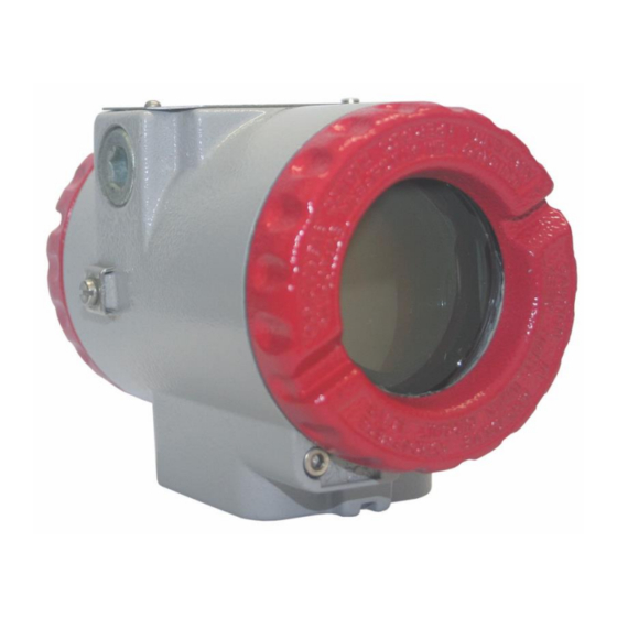
- Page 3 Introduction INTRODUCTION WARNING ® TT400 HART SIS has the housing cover in red to distinguish them from the other line 400 models. ® The TT400 HART SIS is a Smart Temperature Transmitter with 4-20 mA analog output and HART protocol, developed for SIS (Safety Instrumented Systems) applications.
- Page 4 ® TT400 HART SIS - Operation and Maintenance Instruction Manual Acronyms and abbreviations Acronym / Designation Description Abbreviation Hardware Fault The hardware fault tolerance of the device. Tolerance This is the capability of a functional unit to continue the execution of the demanded function in case of faults or deviations.
- Page 5 Smar provides specific training to instruct and qualify such professionals. However, each country must comply with the local safety procedures,...
- Page 6 ® TT400 HART SIS - Operation and Maintenance Instruction Manual...
-
Page 7: Table Of Contents
MAINTENANCE ................................. 3.6 MONITORING - MONIT ............................. 3.7 SECTION 4 - MAINTENANCE PROCEDURES..................4.1 GENERAL................................... 4.1 DIAGNOSES WITH SMAR CONFIGURATOR ......................4.1 ERROR MESSAGES ..............................4.1 DIAGNOSTICS WITH THE CONFIGURATOR ......................4.1 DIAGNOSTICS WITH THE DISPLAY ........................4.2 DISASSEMBLY PROCEDURE ..........................4.2 REASSEMBLY PROCEDURE ........................... - Page 8 ® TT400 HART SIS - Operation and Maintenance Instruction Manual APPENDIX B – SRF – SERVICE REQUEST FORM ................. B.1 APPENDIX C – SMAR WARRANTY CERTIFICATE ................C.1 VIII...
- Page 9 Installation Flowchart Installation Flowchart...
- Page 10 ® TT400 HART SIS - Operation and Maintenance Instruction Manual...
-
Page 11: Section 1 - Installation
WARNING Do not remove the graphite grease from the covers, or they may jam. WARNING The SIS project must be carried through by a professional duly authorized from Smar and qualified for this type of work. WARNING Random, frequent or common cause failures must not damage the equipment´s work or result in death or serious injure, must not harm to the environment or equipment, and must not loss of equipment or production. -
Page 12: Mounting
® TT400 HART SIS– Operation & Maintenance Instruction Manual Mounting The transmitter may be mounted in two basic ways, as follows: - Separated from the sensor, using optional mounting brackets; - Mounted on the sensor assembly. Using the brackets, the mounting may be done in several positions, as shown on Figure 1.1. One of the conduit inlets for electrical connection is used to mount the sensor integral to the temperature transmitter (see Figure 1.1). - Page 13 Installation Figure 1.2 – (a) Cover Locking with Display (b) Cover Locking of the Terminals The Figure 1.3 shows the correct installation of the conduit, in order to avoid entrance of water, or other substance, which may cause malfunctioning of the equipment. Figure 1.3 - Conduit Installation Diagram Cable access to wiring connections is obtained by one of the two conduit outlets.
- Page 14 ® TT400 HART SIS– Operation & Maintenance Instruction Manual GROUND TERMINAL GROUND TERMINALS COMMUNICATION TEST TERMINALS TERMINALS Figure 1.4 - Ground Terminal Use of twisted pair (22 AWG) cables is recommended. WARNING Do not connect the Power Supply to the sensor terminals (Terminals 1, 2, 3 and 4). Avoid routing signal wiring close to power cables or switching equipment.
- Page 15 Installation Figure 1.6 – Load Curve The sensor should be connected as per Figure 1.7. WARNING When operating with two sensors, the sensors can not be both grounded. At least one has to be not ® grounded for proper operation of TT400 HART SIS.
- Page 16 ® TT400 HART SIS– Operation & Maintenance Instruction Manual...
-
Page 17: Section 2 - Operation
Section 2 OPERATION ® The TT400 HART SIS accepts signals from mV generators such as thermocouples or resistive sensors such as RTDs. The criterium is that the signal is within the range of the input. For mV, the range is -50 to 500 mV and for resistance, 0 to 2000 Ohm. -
Page 18: Temperature Sensors
® TT400 HART SIS – Operation and Maintenance Instruction Manual ® The TT400 HART SIS shows failure indication at 3.6 mA if configured for low signal failure or 21 mA if configured for high signal failure; 3.8 mA in the case of low saturation or 20.5 mA in the case of high saturation and measurements proportional to the applied temperature in the range between 3.8 and 20.5 mA. - Page 19 Operation For a correct measurement of RTD temperature, it is necessary to eliminate the effect of the resistance of the wires connecting the sensor to the measuring circuit. In some industrial applications, these wires may be hundreds of meters long. This is particularly important at locations where the ambient temperature changes a lot.
-
Page 20: The Display
® TT400 HART SIS – Operation and Maintenance Instruction Manual Figure 2.4 – Four-Wire Connection A differential connection is similar to the two-wire connection and gives the same problem (see Figure 2.5). The resistance of the other two wires will be measured and does not cancel each other out in a temperature measurement, since linearization will affect them differently. - Page 21 Operation The different fields and status indicators are shown in the picture bellow. Figure 2.7 – Typical Monitoring Mode Display...
- Page 22 ® TT400 HART SIS – Operation and Maintenance Instruction Manual...
-
Page 23: Section 3 - Configuration
Universal Commands, Common Practice Commands and Specific Commands. Smar developed the CONF401 configuration tools, that works in Windows platform (95, 98, 2000, XP, NT and 7). They bring easy configuration and monitoring of field devices, capacity to analyze data and to modify the action of these devices. -
Page 24: Configuring The Tt400 Hart Sis
® TT400 HART SIS - Operation & Maintence Instruction Manual ® Configuring the TT400 HART Operation Modes • Configuration Mode Used transmitter’s configuration. To access this mode, the user must follow the SIS Mode Disabling procedure explained bellow. It is highly recommended to not used the transmitter for SIS application while it is in the Configuration Mode. -
Page 25: Configuration Resources
Configuration Configuration Resources ® ® Through the HART configurators, the TT400 HART SIS allows the following configuration resources to be accessed: Transmitter Identification and Manufacturer Data; Equipment Calibration; Equipment Configuration; Equipment Maintenance. The digital communication between the configurator and the transmitter do not interrupt the temperature measuring and do not disturb the output signal. -
Page 26: Trim
4 mA output. If the signal is 100 percent, the output must be 20 mA. Differences may occur between the SMAR standard current and the plant standard. In this case, the current Trim adjustment should be used. The Configurator will adjust the output signal and then it will ask again if the current is correct or not. -
Page 27: Burnout
Configuration Burnout The burnout may occur when the sensor reading is out of range or the sensor is open. In this case, the transmitter may be adjusted for maximum output limit at 21.0 mA, by configuring it on the upper value, or the minimum limit at 3.6 mA configured on the lower value. -
Page 28: Dual Sensor
® TT400 HART SIS - Operation & Maintence Instruction Manual Dual Sensor The available options are: differential, backup, average, maximum and minimum. ® Differential: In this mode, the TT400 HART SIS will provide the difference between two sensors. Maximum and minimum: the process variable will be supplied by sensor that has the maximum or showed minimum reading, respectively. -
Page 29: Monitoring - Monit
Configuration Monitoring - MONIT Device Variables - This function monitors the transmitter 4 dynamic variables and the output current on the configurator display simultaneously. VARIABLE DESCRIPTION CURRENT mA output Process variable on the selected engineering unit °C Room temperature TEMP Process variable percent Table 3.3 - Monitored Variables Device Status –... - Page 30 ® TT400 HART SIS - Operation & Maintence Instruction Manual...
-
Page 31: Section 4 - Maintenance Procedures
Smar. Diagnoses with Smar Configurator If any problem with the transmitter’s output occurs, it can be investigated by using a configurator, as long as power is supplied and communication and the processing unit are operating normally. -
Page 32: Diagnostics With The Display
® TT400 HART SIS - Operation and Maintenance Instruction Manual Diagnostics with the Display The display can also shows fail messages in the alphanumeric segment. When these messages are shown the transmitter goes automatically to fail safe state. These messages are show in the Table 4.2: DIAGNOSTIC MESSAGES POTENTIAL SOURCE OF PROBLEM F MLK... -
Page 33: Reassembly Procedure
Maintenance Procedures Reassembly Procedure Put input board (8) into housing (18); Tighten input board with its screws (7); Put main board (6) into the housing, ensuring all interconnecting pins are connected; Anchor main board with their screws (5); ... - Page 34 ® TT400 HART SIS - Operation and Maintenance Instruction Manual SPARE PARTS LIST FOR TRANSMITTER CATEGORY DESCRIPTION OF PARTS POSITION CODE (NOTE1) HOUSING, Aluminum (NOTE 2) . 1/2 - 14 NPT 214-0200 . M20 x 1.5 214-0201 . PG 13.5 DIN 214-0202 HOUSING, 316 SS (NOTE 2) .
-
Page 35: Lifetime Transmitter
SD-1 Magnetic tool for local adjustment. Palm* 16 Mbytes Palm Handheld, Including HPC401 initialization and installation software. ® HART interface ( HPI311) for Palm, including the configuration package for Smar transmitters and generic HPC401* transmitters. ® HART interface. HPI311* * For equipment updates and HPC401 software, access our website: http://www.smarresearch.com. - Page 36 ® TT400 HART SIS - Operation and Maintenance Instruction Manual...
-
Page 37: Section 5 - Technical Characteristics
Section 5 TECHNICAL CHARACTERISTICS Functional Specifications Inputs See table 5.1, 5.2 and 5.3; Two-wire, 4-20 mA with superimposed digital communication (HART Protocol Version 5.1/Transmitter/Poll-Response Output Signal mode/Common 4-20 mA). 12 - 55 Vdc; Input with polarization; Power Supply Input with transient suppressor. Liquid crystal display, rotative, with 4 ½... - Page 38 ® TT400 HART SIS – Operation and Maintenance Instruction Manual Physical Specifications 1/2 - 14 NPT, PG 13.5 DIN, and M20 X 1.5 conduit; Electrical Connections Electrical inlet finished in plan face to allow connection sealing by compressing the O’Ring. 2 terminals for power supply connection;...
- Page 39 Technical Characteristics 2, 3 or 4 wires ° MINIMUM C DIGITAL ° ° SENSOR TYPE RANGE RANGE SPAN °C ACCURACY* Cu10 to 250 to 482 ± 1.0 Ni120 to 270 to 518 ± 0.1 Pt50 -200 to 850 -328 to 1562 ±...
-
Page 40: Ordering Code
® TT400 HART SIS – Operation and Maintenance Instruction Manual Ordering Code MODEL SMART TEMPERATURE TRANSMITTER TT400 COD. Communication Protocol HART and 4 to 20 mA COD. Security Option SIS – Safety Instrumented Systems COD. Local Indicator (1) Without Indicator With Digital Indicator COD. - Page 41 Technical Characteristics TT400 / MAIN CODE OF HART TRANSMITTER (CONTINUATION) COD. Burn-out Start Scale (According NAMUR NE43 specifications) (Default) End Scale (According NAMUR NE43 specifications) COD. LCD1 Indication LCD1: Percentage (Default) LCD1: Current - I (mA) LCD1: Temperature (Engineering Unit) COD.
- Page 42 ® TT400 HART SIS – Operation and Maintenance Instruction Manual...
-
Page 43: Section 6 - Safety Instrumented Systems (Sis)
Ugevkqp"8" " SAFETY INSTRUMENTED SYSTEMS (SIS) Safety Instrumented Systems are designed and used to prevent or mitigate hazardous events to protected people, the environment or prevent damage to process equipment. The SIS project is based on the damage that a failure can cause. WARNING The SIS project must be carried by a professional duly qualified for this type of work. - Page 44 ™ VV622"JCTV "UKU"/"Qrgtcvkqp"cpf"Ockpvgpcpeg"Kpuvtwevkqp"Ocpwcn"" Crrnkecvkqp"Uvcpfctfu" Standard Description Electrical apparatus for potentially explosive atmospheres - General GP72236" requirements. Electrical apparatus for potentially explosive atmospheres - Flameproof enclosure ‘d’. GP7223:" Electrical apparatus for potentially explosive atmospheres - Increased safety ‘e’. GP7223;" Electrical apparatus for potentially explosive atmospheres - Intrinsic safety ‘i’.
- Page 45 Vcdng"806"⁄"Hwpevkqpcn"Uchgv{"Xcnwgu" Tgvwtpkpi"Ocvgtkcnu" If it is necessary to return the transmitter and/or Configurator to SMAR, simply contact your local agent or SMAR office, informing this equipment serial number, and return it to our factory. In order to expedite analysis and solution of the problem, the defective item should be returned with a description of the failure observed, with as much details as possible.
- Page 46 ™ VV622"JCTV "UKU"/"Qrgtcvkqp"cpf"Ockpvgpcpeg"Kpuvtwevkqp"Ocpwcn"" 806"...
-
Page 47: Hazardous Locations Certifications
CERTIFICATION INFORMATION Hazardous Locations Certifications NOTE The IP68 sealing test (immersion) was performed at 1 bar for 24 hours. For any other situation, please consult Smar. South America Certification INMETRO approvals Certificate No: CEPEL- Ex-1979/10X Intrinsically safe - Ex-ia IIC T4/T5/T6... - Page 48 ® TT400 HART SIS – Operation and Maintenance Instruction Manual • Identification of Intrinsically Safe and Explosion Proof for gas and steam:...
- Page 49 E-mail: Date: Signature: For warranty or non-warranty repair, please contact your representative. Further information about address and contacts can be found on www.smar.com/contactus.asp. NOTA ® (1) This field should be filled out by the Smar. (3) Required for Wireless HART devices.
- Page 50 FSR – FORMULÁRIO PARA SOLICITAÇÃO DE REVISÃO...
- Page 51 Appendix C SMAR WARRANTY CERTIFICATE SMAR guarantees its products for a period of 24 (twenty four) months, starting on the day of issuance of the invoice. The guarantee is valid regardless of the day that the product was installed. SMAR products are guaranteed against any defect originating from manufacturing, mounting,...
- Page 52 13. It is the customer’s responsibility to clean and decontaminate products and accessories prior to shipping them for repair, and SMAR and its dealer reserve themselves the right to refuse the service in cases not compliant to those conditions. It is the customer’s responsibility to tell SMAR and its dealer when the product was utilized in applications that contaminate the equipment with harmful products during its handling and repair.
Need help?
Do you have a question about the TT 400 SIS and is the answer not in the manual?
Questions and answers