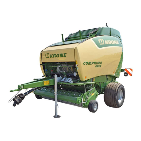
Krone Comprima V 180 Original Operating Instructions
Round baler
Hide thumbs
Also See for Comprima V 180:
- Original operating instructions (430 pages) ,
- Original operating manual (234 pages) ,
- Original operating instructions (366 pages)

Related Manuals for Krone Comprima V 180


Summary of Contents for Krone Comprima V 180
- Page 1 Original Operating Instructions Document no.: 150001053_00_en RP701-40 Round Baler Comprima V 180 From machine no.: 995323...
- Page 2 Contact Maschinenfabrik Bernard Krone GmbH & Co. KG Heinrich-Krone-Straße 10 48480 Spelle Germany Telephone switchboard + 49 (0) 59 77/935-0 Telefax switchboard + 49 (0) 59 77/935-339 Telefax spare parts warehouse do- + 49 (0) 59 77/935-239 mestic Telefax spare parts warehouse export + 49 (0) 59 77/935-359 Internet www.landmaschinen.krone.de...
-
Page 3: Table Of Contents
Function description net wrapping ..................... 37 Function description net and chamber film wrapping .............. 38 Function description of the bale formation conveyor stop ............ 39 Technical data .......................... 40 Consumables .......................... 41 5.1.1 Oils............................. 42 Comprima V 180 Original Operating Instructions 150001053_00_en... - Page 4 Connecting the KRONE ISOBUS terminal (CCI 1200) .............. 61 7.10 Connecting foreign ISOBUS terminal .................. 63 7.11 Connecting the camera to the KRONE ISOBUS terminal CCI 1200 ......... 64 7.12 Connecting the road lighting ...................... 64 7.13 Mounting safety chain ........................ 65 Operation ..........................
- Page 5 10.2 Switching terminal on/off...................... 97 10.3 Design of display ........................ 98 10.4 Design of the KRONE machine application ................ 98 10.5 Setting units on the terminal ...................... 99 Foreign ISOBUS terminal ...................... 100 11.1 ISOBUS Shortcut Button not available .................. 100 11.2...
- Page 6 Drive chain of the intake ...................... 182 16.17.3 Drive chain of the bale formation conveyor ................ 183 16.17.4 Drive chain of the auger conveyors .................. 184 16.17.5 Drive chain of the rollers ...................... 185 Comprima V 180 Original Operating Instructions 150001053_00_en...
- Page 7 Setting the tailgate lock...................... 224 Repairs, maintenance and settings by technicians ............ 226 Storage............................ 227 Waste disposal........................ 230 Appendix.......................... 231 21.1 Hydraulic diagram ........................ 231 21.2 Circuit diagram......................... 231 Index............................ 232 Declaration of conformity ..................... 241 Comprima V 180 Original Operating Instructions 150001053_00_en...
-
Page 8: Information On This Document
Information on This Document Validity This document is valid for machines of type: RP701-40 (Comprima V 180) All information, illustrations and technical data in this document correspond to the latest state at the time of publication. We reserve the right to make design changes at any time and without notification of reasons. -
Page 9: Figures
H = height, L = length) Left-hand side of the machine Right-hand side of the machine side Direction of travel Moving direction Reference line for visible material Reference line for covered mater- Centre line Cable routes Comprima V 180 Original Operating Instructions 150001053_00_en... - Page 10 When cleaning with compressed air, dirt particles are ejected at high speed and could get into the eyes. Therefore eyes could be hurt. „ Keep people away from the working area. „ Wear personal protective equipment when performing cleaning work with compressed air (e.g. eye protection). Comprima V 180 Original Operating Instructions 150001053_00_en...
-
Page 11: Conversion Table
Horsepower Pressure Kilopascal 0.1450 Pounds per square inch Megapascal 145.0377 bar (non-SI) 14.5038 Torque Newtonmeter 0.7376 pound-foot or ft∙lbf foot-pound 8.8507 pound-inch or in∙lbf inch-pound Temperature Degrees Celsius °C °Cx1.8+32 Degrees °F Fahrenheit Comprima V 180 Original Operating Instructions 150001053_00_en... - Page 12 Kilometres per km/h 0.6215 Miles per hour hour Volumes Litres 0.2642 US gallon US gal. Millilitre 0.0338 US ounce US oz. Cubic centi- cm³ 0.0610 Cubic inch in³ metre Weight Kilogram 2.2046 Pound Comprima V 180 Original Operating Instructions 150001053_00_en...
-
Page 13: Safety
• Attachment of unauthorised or unapproved additional equipment • Use of spare parts which are not KRONE original spare parts • Stationary operation of the machine Unauthorised modifications to the machine may affect the properties of the machine or disrupt proper operation. -
Page 14: Service Life Of The Machine
He has read the operating instructions and can implement the information in the operating instructions accordingly. • He is familiar with driving vehicles safely. • For road travel he has adequate knowledge of the highway code and has the stipulated driving licence. Comprima V 180 Original Operating Instructions 150001053_00_en... -
Page 15: Personnel Qualification Of The Technicians
Additional equipment and spare parts that do not correspond to the requirements of the manufacturer may affect the operational safety of the machine and cause accidents. „ To ensure operational safety, use original parts or standard parts which correspond to the requirements of the manufacturer. Comprima V 180 Original Operating Instructions 150001053_00_en... -
Page 16: Jobs On The Machine
„ In case of damage which may affect operational safety and cannot be repaired according to these operating instructions: Have damage repaired by a qualified service centre. Comprima V 180 Original Operating Instructions 150001053_00_en... -
Page 17: Danger Zones
This also applies to brief inspection work. „ Consider the information in all relevant operating instructions: • The operating instructions of the tractor • The operating instructions of the machine • The operating instructions of the universal shaft Comprima V 180 Original Operating Instructions 150001053_00_en... - Page 18 „ In case of dangerous situations, immediately switch off drives and instruct persons to leave the danger zone. Danger zone due to trailing machine parts If machine parts are trailing, people may be seriously injured or killed. Comprima V 180 Original Operating Instructions 150001053_00_en...
-
Page 19: Ensuring Functionality Of Safety Devices
„ Make sure every time after cleaning the safety labels that they are complete and legible. „ Immediately replace missing, damaged and unrecognizable safety labels. „ Provide spare parts with intended safety labels. Descriptions, explanations and order numbers of safety labels,refer to page 27. Comprima V 180 Original Operating Instructions 150001053_00_en... -
Page 20: Road Safety
„ Avoid abrupt steering movements on slopes. „ On slopes always deposit a round bale in such a way that it cannot move on its own. „ Do not park the machine on slopes. Comprima V 180 Original Operating Instructions 150001053_00_en... -
Page 21: Parking The Machine Safely
„ Check and clean the machine every day before using it for the first time. „ Check and clean the machine regularly during the working day. Comprima V 180 Original Operating Instructions 150001053_00_en... -
Page 22: Sources Of Danger On The Machine
„ Specify rules for the use of hearing protection and for the working time. „ During operation keep windows and doors of cabin closed. „ Remove hearing protection for road travel. Liquids under high pressure The following liquids are under high pressure: • Hydraulic oil Comprima V 180 Original Operating Instructions 150001053_00_en... -
Page 23: Dangers In Connection With Certain Activities: Working On The Machine
Thus there is a risk of serious injuries or death. „ Before carrying out any repair, maintenance and cleaning work on the machine, shutdown and safeguard it, refer to page 25. Comprima V 180 Original Operating Instructions 150001053_00_en... -
Page 24: Dangers In Connection With Certain Activities: Working On Wheels And Tyres
The fitting of wheels and tyres requires adequate knowledge and approved mounting tools. „ If there is a lack of knowledge, have the wheels and tyres fitted by the KRONE dealer or by a qualified tyre service. -
Page 25: Behaviour In Dangerous Situations And In Case Of Accidents
„ Before working on or under raised machine parts: Secure machine or machine parts against lowering by means of hydraulic shut-off device (e.g. stop cock) on machine side. „ Before working on or under raised machine parts: Safely support machine or machine parts. Comprima V 180 Original Operating Instructions 150001053_00_en... -
Page 26: Carrying Out Oil Level Check And Oil And Filter Element Changes Safely
„ Lower raised machine parts or secure them against falling, refer to page 25. „ Shut down and secure the machine, refer to page 25. „ Cordon off the danger zone of the actuated moving machine parts in a clearly visible manner. Comprima V 180 Original Operating Instructions 150001053_00_en... -
Page 27: Safety Labels On The Machine
Safety labels on the machine Every safety label is provided with an order number and can be ordered directly from the authorised KRONE dealer. Immediately replace missing, damaged and unrecognisable safety labels. When attaching safety labels, the contact surface on the machine must be clean and free of dirt, oil and grease to ensure optimum adhesion of the labels. - Page 28 Safety Safety labels on the machine Position and meaning of safety labels RPG000-064 Comprima V 180 Original Operating Instructions 150001053_00_en...
- Page 29 There is a danger of being drawn in if you ap- proach the danger zone and if you use your hands or feet to remove crop blockages. „ Before working on the pick-up, switch off the PTO shaft and the engine. Comprima V 180 Original Operating Instructions 150001053_00_en...
- Page 30 Risk of injury due to rolling away or tilting ma- chine. „ Before opening the tailgate, make sure that the machine is correctly attached to the tractor. „ When uncoupling the machine, ensure that the tailgate is closed. Comprima V 180 Original Operating Instructions 150001053_00_en...
- Page 31 „ Observe the notes in the operating instructions before removing and repairing the pressure accumulator. „ The pressure accumulator must only be removed and repaired by a specialist workshop. Comprima V 180 Original Operating Instructions 150001053_00_en...
-
Page 32: Safety Equipment
• The attachment of the safety chain is not stipulated in all countries. • The country-specific regulations for using the safety chain during transportation of the machine must be observed. Comprima V 180 Original Operating Instructions 150001053_00_en... -
Page 33: Smv Emblem
The SMV emblem (Slow-Moving Vehicle) (1) can be mounted on slow-moving machines or vehicles. The country-specific specifications must be observed. The SMV emblem (1) is at the rear in the centre or on left. Comprima V 180 Original Operating Instructions 150001053_00_en... - Page 34 Safety Safety equipment If the machine is transported on transport vehicles (for example lorry or train), the SMV emblem must be covered or dismounted. Comprima V 180 Original Operating Instructions 150001053_00_en...
-
Page 35: Data Memory
- if applicable in consultation with an expert. Additional functions regulated by a contractual agreement with the customer (e.g. remote maintenance) permit the transmission of certain machine data from the machine. Comprima V 180 Original Operating Instructions 150001053_00_en... -
Page 36: Machine Description
Pick-up drive To prevent an overload, there is a cam clutch on the pick-up drive. This cam clutch has been set at the factory and must not be adjusted without consulting your KRONE service partner. Comprima V 180 Original Operating Instructions 150001053_00_en... -
Page 37: Identification Plate
To ensure that these data are always available, we recommend to enter them in the fields on the front cover page of these operating instructions. Function description net wrapping RP000-533 Comprima V 180 Original Operating Instructions 150001053_00_en... -
Page 38: Function Description Net And Chamber Film Wrapping
15 Deflection roll on the cross tube 7 Retaining sheet 16 Feed rocker arm 8 Feed strips 17 Spherical button for locking the tension lever 9 Wrapping material path of net or film 18 Tension lever Comprima V 180 Original Operating Instructions 150001053_00_en... -
Page 39: Function Description Of The Bale Formation Conveyor Stop
On extreme slopes, depositing of the bale can be prevented by the tailgate. When the tailgate is opened, the coupling is automatically actuated via an actuating lever and the wire rope and the bale formation conveyor is switched off. Comprima V 180 Original Operating Instructions 150001053_00_en... -
Page 40: Technical Data
165 bar Operating pressure of hydraulic system (max.) 200 bar Max. oil temperature 80 °C Minimum oil quality Oil ISO VG 46 Delivery capacity hydraulics (min.) 30 L/min Delivery capacity hydraulics (max.) 60 L/min Comprima V 180 Original Operating Instructions 150001053_00_en... -
Page 41: Consumables
If types of oil are mixed, the machine could be damaged. „ Never mix different types of oil. „ Before changing the type of oil, consult customer service. Never use engine oil. Biodegradable consumables can be used on request. Comprima V 180 Original Operating Instructions 150001053_00_en... -
Page 42: Oils
Lubricating greases For the manual lubrication points, a lubricating grease pursuant to DIN 51818 of NLGI class 2 (lithium soap with EP additives) must be used. KRONE recommends not to use lubricating greases based on other substances. The filling quantity depends on the requirements. Lubricate the manual lubrication points until lubricating grease escapes at the bearing position. -
Page 43: Initial Operation
„ The safety routines must be read and observed to avoid accidents, refer to page 25. Scope of delivery The machine is delivered with the following additional parts which are in the storage compartment, under the machine or on the pick-up. Comprima V 180 Original Operating Instructions 150001053_00_en... - Page 44 14.4 Springs 8 Mounting material 14.5 Strips 9 Can of spray paint 14.6 Screws 10 Warning foil 14.7 Springs with clamping screws 11 Test roll KRONE excellent, net for net 14.8 Spacer wrapping Comprima V 180 Original Operating Instructions 150001053_00_en...
-
Page 45: Mounting Hose And Cable Support
„ Remove the duct tape (1) provided as corrosion protection from the surface of the brake disc (2) and discard. Checking/adapting the tyre pressure Before the initial operation, check and adjust the tyre pressure. A label at the PTO shaft end draws the attention to this important test: Comprima V 180 Original Operating Instructions 150001053_00_en... -
Page 46: Adjusting The Drawbar Height
„ To ensure optimum operating conditions, hitch the machine so that the dimension X matches the aforementioned values. ð If the measured dimension differs from dimension X, adjust the drawbar height as follows. Comprima V 180 Original Operating Instructions 150001053_00_en... -
Page 47: Universal Shaft
The machine could be damaged if the universal shaft length is not checked when changing the tractor. „ In order to avoid damage to the machine, check universal shaft length every time the tractor is changed and correct it, if necessary, refer to page 47. RPG000-086 Comprima V 180 Original Operating Instructions 150001053_00_en... -
Page 48: Mounting Protective Cap Of Universal Shaft
6.6.3 Mounting universal shaft bracket RP000-486 The universal shaft bracket (1) is only required if the drawbar is in the bottom hitching. ü The machine is shut down and safeguarded, refer to page 25. Comprima V 180 Original Operating Instructions 150001053_00_en... -
Page 49: Mounting The Universal Shaft On The Machine
„ Push the universal shaft (1) onto the PTO shaft end of the machine. „ Mount the screw connection (2) through the resulting hole behind the cover (6). „ Mount the cover (6). „ Hook the universal shaft chain (5) into the eye (4) on the protective cap (3). Comprima V 180 Original Operating Instructions 150001053_00_en... -
Page 50: Mounting The Bale Ejector
„ Secure the bolts (5) on the right and left of the bale ejector (2) with a disc (4) and clamping sleeve (3). „ Tighten the screw connections (1) of the mounting plates on the right and left side of the bale ejector (2). Comprima V 180 Original Operating Instructions 150001053_00_en... - Page 51 „ Make sure that the screw (6) is not secured too tightly. The screw (6) must be flush with the locknut (8). „ Fit a screw (2), springs (3), disc (4) and locknut (5). „ Place the bale ejector on the machine. Comprima V 180 Original Operating Instructions 150001053_00_en...
- Page 52 „ Hook the eye bolt (3) into the tension spring (2) and guide it through the bore hole (5). „ Secure with the disc and nut (4). „ Tighten the nut (4) until the bale ejector swings safely into the basic setting after depositing the round bale. Comprima V 180 Original Operating Instructions 150001053_00_en...
- Page 53 „ Mount the spacer (1) with the round-head screws, discs and nuts on the bale ejector (2). For "single axis" version RP000-501 The under side of the bale ejector is shown. „ Mount 2 support plates (1) with screws and washers on the under side of the bale ejector. Comprima V 180 Original Operating Instructions 150001053_00_en...
-
Page 54: Commissioning
(e.g. tractor tyres). „ Couple and connect the hoses and cables to the designated connections as described in the operating instructions. Connecting machine to tractor RP000-098 Example image Comprima V 180 Original Operating Instructions 150001053_00_en... -
Page 55: Mounting The Universal Shaft On The Tractor
ü The machine is shut down and safeguarded, refer to page 25. RPG000-096 „ Push the universal shaft (1) onto the tractor PTO shaft. Comprima V 180 Original Operating Instructions 150001053_00_en... -
Page 56: Connecting Hydraulic Hoses
„ When connecting the quick couplings, ensure that they are clean and dry. „ Check the hydraulic hoses for abrasion and pinch point and replace if required. RP000-493 To connect the hydraulic hoses (1) correctly, the hydraulic hoses (1) are marked with numbers. Comprima V 180 Original Operating Instructions 150001053_00_en... -
Page 57: Connecting Hydraulic Brake (Export)
For this an additional single-action control valve is required. The brake is activated by actuating the control valve. The pressure can be adjusted with the machine's pressure limiting valve. The pressure limiting valve is set to approx. 50 bar. Comprima V 180 Original Operating Instructions 150001053_00_en... -
Page 58: Connecting/Disconnecting Compressed Air Connections For The Compressed Air Brake
Observe the correct order when disconnecting the compressed air lines. „ Firstly, disconnect the supply line (2) (red coupling head). „ Then disconnect the brake line (1) (yellow coupling head). Adjusting drawbar eye For "drawbar eye bottom" version RP000-266 Comprima V 180 Original Operating Instructions 150001053_00_en... -
Page 59: Connecting Krone Beta Ii-Terminal
ü The machine is shut down and safeguarded, see chapter Safety, "Shutting down and safeguarding the machine". ü The accessories kit B290 “KRONE tractor retrofitting” is mounted. Connection terminal to tractor „ Connect the 9-pin plug (1) of the terminal to the 9-pin socket (2) (In-cab). - Page 60 Commissioning Connecting KRONE BETA II-Terminal Connection tractor to machine INFORMATION For the "Comfort Electronics" version To connect the terminal, follow the instructions in the accessories kit B121 "Cable set for CCI- Terminal". INFORMATION The cable (5) can be ordered by quoting the order number 20 085 866 *.
-
Page 61: Connecting The Krone Isobus Terminal (Cci 1200)
Commissioning Connecting the KRONE ISOBUS terminal (CCI 1200) Connection tractor to machine INFORMATION The cable (5) can be ordered by quoting the order number 20 085 866 *. „ Connect the 9-pin plug (4) of the cable (5) to the 9-pin ISOBUS socket (3) of the tractor. - Page 62 ü The machine is shut down and safeguarded, refer to page 25. ü The accessories kit B290 “KRONE tractor retrofitting” is mounted. Connection terminal to tractor „ Connect the 12-pin plug (2) of the cable (3) to the 12-pin socket (1) of the terminal.
-
Page 63: Connecting Foreign Isobus Terminal
„ Connect the 11-pole socket (4) of the cable (2) to the 11-pole socket (3) of the machine. Connection terminal to tractor INFORMATION For further details on terminal connection, observe operating instructions of ISOBUS terminal manufacturer. Comprima V 180 Original Operating Instructions 150001053_00_en... -
Page 64: Connecting The Camera To The Krone Isobus Terminal Cci 1200
Connecting the camera to the KRONE ISOBUS terminal CCI 1200 EQ000-212 „ Insert the plug (4) on the camera (2) cable (3) into the connection C (6) of the KRONE ISOBUS terminal CCI 1200 (1). „ To connect the plug (4) correctly, ensure that it is aligned with the marked points (5). -
Page 65: Mounting Safety Chain
ü The machine is shut down and safeguarded, refer to page 25. RP000-104 DV000-016 „ Install the safety chain (1) at a suitable position (for example: [I] or [II]) on the tractor. Comprima V 180 Original Operating Instructions 150001053_00_en... -
Page 66: Operation
„ Press only round bales which do not exceed the set baling pressure and bale diameter. „ Observe the following information on the even filling of the bale chamber. Comprima V 180 Original Operating Instructions 150001053_00_en... - Page 67 If the crops are very wet and have little structure, this may increase slippage of the bale formation conveyor. This can be reduced by taking the following measures: „ Reduce the baling pressure, refer to page 146. „ Setting a low bale core density, refer to page 147. Comprima V 180 Original Operating Instructions 150001053_00_en...
-
Page 68: Improving Bale Chamber Filling
„ Setting a low bale core density, refer to page 147. „ Start the tying cycle earlier than indicated. Driving speed KRONE recommends a driving speed of 5-12 km/h The driving speed during the work must be adapted to the following conditions: • Type of crops •... -
Page 69: Mounting Additional Deflector Sheets In The Tailgate
Before starting baling work, the bale formation conveyors must be moved into the working position and hydraulically clamped. After finishing baling work, the bale formation conveyors must be moved for protection back into the parking position and declamped. Comprima V 180 Original Operating Instructions 150001053_00_en... -
Page 70: Operating The Support Jack
The support jack is used to keep the machine stable when it is not connected to the tractor. The support jack must be used whenever the machine is parked. ü The machine is shut down and safeguarded, refer to page 25. ü The machine is connected to the tractor,refer to page 54. Comprima V 180 Original Operating Instructions 150001053_00_en... - Page 71 „ Pull out the securing pin (4), push in the support jack (2) and secure the position with the securing pin (4). „ Turn the support jack (2) clockwise all the way up using the crank handle (1). „ Rotate the support plate (3) so that the flat side points towards the pick-up. Comprima V 180 Original Operating Instructions 150001053_00_en...
- Page 72 WARNING! Crush hazard due to support jack swinging down! Swivel the support jack up or down using the handle (4) only. „ Insert the bolt (1) through the boreholes (5, 6) and secure it in the locking spring (7). Comprima V 180 Original Operating Instructions 150001053_00_en...
-
Page 73: Using The Stop Cock Of The Tailgate
Æ The tailgate can be closed. Closing the stop cock „ Raise the stop cock (1) and move it to position (II). Æ The tailgate cannot be closed. Releasing/applying the parking brake RP000-398 Comprima V 180 Original Operating Instructions 150001053_00_en... -
Page 74: Fitting Wheel Chocks
„ Ensure that the safety cable (1) cannot slip or become detached. Fitting wheel chocks RPG000-012 The wheel chocks (1) secure the machine against rolling away. 2 wheel chocks are affixed to the machine. Comprima V 180 Original Operating Instructions 150001053_00_en... -
Page 75: Pick-Up
„ To preselect the pick-up, press the key on the terminal, refer to page 103. ð The key switches to „ To lift the pick-up into the transport position, actuate the control unit on the tractor (yellow, 3+). Comprima V 180 Original Operating Instructions 150001053_00_en... -
Page 76: Setting The Pick-Up Working Height
ü The machine is shut down and safeguarded, refer to page 25. ü The pick-up is fully raised in transport position, refer to page 75. ü The guide wheels are folded upwards. Comprima V 180 Original Operating Instructions 150001053_00_en... -
Page 77: Adjusting The Bearing Pressure Relief For The Pick-Up
To be able to negotiate uneven ground better, the pick-up is relieved on both sides of the machine with the aid of a spring (3). The spring (3) can be set on the ring screw (2). KRONE recommends the following setting: • Dimension X (left side of machine): 150 mm •... -
Page 78: Setting The Crop Press Roller Unit
The height of the baffle sheet (1) on the crop press roller unit can be adjusted to the swath. Position (I) has been set at the factory. If the crops are very moist, it is recommended to move the baffle sheet into position (II). Comprima V 180 Original Operating Instructions 150001053_00_en... -
Page 79: Removing/Mounting The Baffle Sheet On The Crop Press Roller Unit
Removing crop blockages: refer to page 88 RP000-139 ü The machine is shut down and safeguarded, refer to page 25. Comprima V 180 Original Operating Instructions 150001053_00_en... -
Page 80: Net Wrapping
Also observe the information on the package provided by the tying material manufacturer. INFORMATION For trouble-free use in the field, KRONE recommends one of the "KRONE excellent" nets, see label on the machine with the number 27 018 640 *. RPG000-016 ü... -
Page 81: Insert Net
„ Always wear protective gloves when inserting the wrapping and tying material and when working in the range of the cutting unit. „ When working in the range of the cutting unit, work particularly carefully and prudently. Comprima V 180 Original Operating Instructions 150001053_00_en... -
Page 82: Net And Chamber Film Wrapping
If a sleeve is made of plastic with grooves, the sleeve clamp can dig into the grooves and transfer the brake force from the brake disc to the net or film roll. Therefore, plastic sleeves without grooves are not recommended. Comprima V 180 Original Operating Instructions 150001053_00_en... - Page 83 INFORMATION For trouble-free use in the field, KRONE recommends one of the "KRONE excellent" nets or films, see label on the machine with the number 27 018 640 *. ü The machine is shut down and safeguarded, refer to page 25.
-
Page 84: Inserting The Net Or Film
„ Move the feed rocker arm (3) on the terminal in the feed position direction of arrow until there is a distance of approx. 5 cm between the spreading roll (1), covered with red foam, and the tapered roller (2), refer to page 125. Comprima V 180 Original Operating Instructions 150001053_00_en... - Page 85 The tension lever (12) must touch and guide the wrapping material roll (1). To do this, the tension lever (12) must be released, refer to page 152. • The conical roller (3) must be locked to prevent it from rotating during net wrapping, refer to page 153. Comprima V 180 Original Operating Instructions 150001053_00_en...
-
Page 86: Notes On Operation
If possible, for initial operation, use a complete net roll first and tie the round bales with net. This procedure can be used to remove any sharp edges or paint residue beforehand. • KRONE recommends not to use chamber film wrapping for straw bales. There is a risk of condensation forming, resulting in mould. •... -
Page 87: Using The Bale Ejector
INFORMATION KRONE recommends 3.5-4 film layers to ensure optimum chamber film wrapping, refer to page 119. The minimum required film layers depend on the condition of the crops. For round bales with a diameter greater than 130 cm and/or very dry or very wet crops, KRONE recommends using at least one additional film layer. -
Page 88: Removing Crop Blockages
After the round bale has been laid down, the bale chamber is closed and whilst new crops are being taken in, the bale ejector must be positioned again on the axis. „ Have the setting of the bale ejector be checked by a KRONE service partner. 8.15 Removing crop blockages 8.15.1... -
Page 89: Operating The Reversing Device With Crop Blockages
WARNING! Risk of injury or damage to the machine from an attached actuating lever (2) when putting the machine back into operation! To avoid injuries, remove the actuating lever (2) and place in the storage compartment. „ Close the cover (1). Comprima V 180 Original Operating Instructions 150001053_00_en... - Page 90 „ Close the stop cock (3) in the control valve hydraulic hose line. „ Manually remove any remaining crop from the feed rotor (1) or the pick-up. „ Start the engine and turn on the PTO shaft. Comprima V 180 Original Operating Instructions 150001053_00_en...
-
Page 91: Operating The Central Chain Lubrication System
To service the central chain lubrication system, refer to page 188. Dosing units on right side of machine RPG000-077 The dosing units on the rail on the right side of the machine oil the chains of the following machine components: Comprima V 180 Original Operating Instructions 150001053_00_en... - Page 92 Bale formation conveyor drive at front Roller drive feed roller Pick-up/auger conveyor Setting oil quantity „ Loosen the screws (6). „ Turn the eccentric cam (7) until the arrow is on the required oil quantity. „ Tighten the screws (6). Comprima V 180 Original Operating Instructions 150001053_00_en...
-
Page 93: Krone Beta Ii Terminal
ISOBUS Shortcut Button not available EQG000-022 The KRONE Beta II terminal does not feature an ISOBUS shortcut button. Icon (1) is shown on the display. The ISOBUS shortcut button is not available to switch off machine functions. Comprima V 180... -
Page 94: Switching Terminal On/Off
KRONE Beta II terminal Switching terminal on/off Switching terminal on/off EQ001-029 „ Before switching on the terminal for the first time, check that the connections are correct and tight. Switching on „ Move the toggle switch (1) from position I to position II. -
Page 95: Design Of Display
KRONE Beta II terminal Design of display Design of display EQ001-033 The display of the terminal is divided up into the following sections: Status line (1) The status line (1) indicates current states of the machine (depending on how it is equipped), refer to page 102. -
Page 96: Krone Isobus Terminal (Cci 1200)
KRONE machines, which have ISOBUS equipment, are coordinated with this system. EQG000-057 The electronic equipment of the machine consists essentially of the job computer (1), the terminal (2) and the control and function elements. -
Page 97: Switching Terminal On/Off
KRONE ISOBUS terminal (CCI 1200) Switching terminal on/off 10.2 10.2 Switching terminal on/off EQ001-174 „ Before switching on the terminal for the first time, check that the connections are correct and tight. INFORMATION When the terminal is switched on for the first time, the machine configuration is loaded into the terminal and saved in the terminal memory. -
Page 98: Design Of Display
„ For more details on how the terminal functions, follow the terminal operating instructions. 10.4 Design of the KRONE machine application EQG000-059 The KRONE machine application is divided into the following areas: Status line (1) The status line (1) indicates current states of the machine (depending on how it is equipped), refer to page 102. -
Page 99: Setting Units On The Terminal
KRONE ISOBUS terminal (CCI 1200) Setting units on the terminal 10.5 Main window (3) Values (figures) shown in blue in the main window can be selected using the touch function. There are the following main window views: • Road travel screen •... -
Page 100: Foreign Isobus Terminal
When using terminals and other operation units which have not been delivered by KRONE mind that the user: ü assumes the responsibility for the use of KRONE machines when using the machine on operation units (terminal / other operating elements) which have not been delivered by KRONE. -
Page 101: Varying Functions To Krone Isobus Terminal
The job computer provides information and control functions of the machine on the display of the external ISOBUS terminal. Operation with an external ISO terminal is similar to the KRONE ISOBUS terminal. Prior to start-up, refer to the mode of operation of the KRONE ISOBUS terminal in the operating instructions. -
Page 102: Terminal Machine Functions
„ Remedy the malfunction when the error message is displayed, refer to page 200. „ If the malfunction cannot be remedied, consult a KRONE service partner. 12.1 Status line INFORMATION Using a terminal with a resolution of less than 480x480 pixels. -
Page 103: Keys
The previously selected mode (manual manual mode. mode or automatic mode) is displayed in the set tying type. Press the key to change the mode. Chamber film wrapping in automatic mode. Work lighting Switching off Switching ON Comprima V 180 Original Operating Instructions 150001053_00_en... -
Page 104: Displays On The Working Screen
Set baling pressure (for version with "Electronic baling pressure adjust- ment"). The TIM status indicates the successful connection between tractor and machine. The machine automatically takes over control of the TIM func- tions on the tractor, refer to page 108. Comprima V 180 Original Operating Instructions 150001053_00_en... - Page 105 Icons during the net or chamber film wrapping process Icon Explanation Value of bale diameter/baling pressure is reached (flashing) Net/film is fed. Net/film has not been tied. Net/film tying process is active. Net/film tying process is stopped. Comprima V 180 Original Operating Instructions 150001053_00_en...
-
Page 106: Accessing The Working Screen
From the road travel screen „ Press Æ The working screen is shown, refer to page 104. From each menu ü One menu is called up. „ Press longer. 12.5 Automatic call of the Road travel screen EQG000-026 Comprima V 180 Original Operating Instructions 150001053_00_en... -
Page 107: Adjusting Bale Diameter
Adjusting the bale diameter via the touch-capable display „ Tap the blue value to be changed. ð An input field opens. „ Enter the desired value and press ð The value is saved and the input field exited. Comprima V 180 Original Operating Instructions 150001053_00_en... -
Page 108: Operating Tim 1.0 (Tractor Implement Management)
12.7.2 TIM displays and keys on the working screen ∑ 100% 0 cm EQG003-096 The following TIM displays are possible: Comprima V 180 Original Operating Instructions 150001053_00_en... -
Page 109: Activating Tim Functions
To activate the TIM functions, only the connection between machine and tractor must be established. ü In menu 14-5 "Configuring TIM software"(refer to page 129) • the required TIM functions were selected and Comprima V 180 Original Operating Instructions 150001053_00_en... -
Page 110: Pausing Tim Functions
ü The TIM status on the working screen is on „ Press Æ The TIM functions are paused and must be operated manually via the tractor control units. The TIM status switches to „ To reactivate the TIM functions, refer to page 109. Comprima V 180 Original Operating Instructions 150001053_00_en... - Page 111 „ To deactivate the TIM function "Opening and closing tailgate at the end of the tying cycle", select the checked checkbox next to the icon Æ The checkbox is empty and the TIM function has been deactivated. Comprima V 180 Original Operating Instructions 150001053_00_en...
-
Page 112: Terminal Menus
(for the “Net and chamber film wrapping” version), refer to page 122 Filling correction, refer to page 123 Manual operation, refer to page 124 Counter, refer to page 126 13-1 Customer counter, refer to page 126 ∑ 13-2 Total counter, refer to page 128 ∑ Comprima V 180 Original Operating Instructions 150001053_00_en... -
Page 113: Recurring Icons
Move to the left in order to select some- thing. Disk Save the setting. Leave menu without saving. By pressing the key longer, the previously viewed working screen is called up. Reset to factory setting. Comprima V 180 Original Operating Instructions 150001053_00_en... -
Page 114: Selecting A Menu Level
„ To select a menu, press the keys next to until the desired menu is selected. ð The selected menu is highlighted in colour. „ To call up the menu, press the key next to Æ The menu opens. Comprima V 180 Original Operating Instructions 150001053_00_en... -
Page 115: Changing Value
If a numeric value is tipped, an input mask opens. For further information on entering values in the input mask, refer to the enclosed operating instructions of the terminal. Examples: By means of the scroll wheel „ Choose the desired value by using the scroll wheel. Comprima V 180 Original Operating Instructions 150001053_00_en... -
Page 116: Changing Mode
Æ An acoustic signal sounds, the set mode is saved and the icon is briefly displayed in the upper line. „ To leave the menu, press 13.7 Tying in the menu level ü For The menu level is active, refer to page 114. Comprima V 180 Original Operating Instructions 150001053_00_en... - Page 117 Tying start delay net wrapping (if ‘net’ has been selected as the type of tying under (3)) Tying start delay twine tying (if ‘twine’ has been selected as the type of tying under (3)) Select type of tying (net or twine) Comprima V 180 Original Operating Instructions 150001053_00_en...
-
Page 118: Menu 1 "Number Of Net Layers" (Net Wrapping)
„ To open the menu, press Æ The display shows menu “Number of net layers”. Adjusting the number of net layers „ Increase or decrease the value, refer to page 115. „ To save the value, press Comprima V 180 Original Operating Instructions 150001053_00_en... -
Page 119: Menu 1 "Number Of Film Layers" (Chamber Film Wrapping)
„ To save the value, press INFORMATION KRONE recommends 3.5 – 4 film layers for optimum chamber film wrapping. The minimum required film layers depend on the condition of the crops. With round bales whose diameter measures more than 130 cm and/or very dry or very wet crops, KRONE recommends at least one additional film layer. -
Page 120: Menu 4 "Tying Start Delay" (Net Wrapping)
ü For the “Net and chamber film wrapping” version: Net wrapping is selected in menu 8 “Type of tying”, refer to page 122. „ To open the menu, press Æ The display shows menu “Tying start delay”. Comprima V 180 Original Operating Instructions 150001053_00_en... -
Page 121: Menu 4 "Tying Start Delay" (Chamber Film Wrapping)
Æ The display shows menu “Tying start delay”. Special feature of chamber film wrapping The tying start delay is automatically set to 0.0 s for chamber film wrapping. KRONE recommends this setting. At high driving speeds, the tying start delay can be set to a minimum for chamber film wrapping: „... -
Page 122: Menu 8 "Type Of Tying" (For The "Net And Chamber Film Wrapping" Version)
ü For The menu level is active, refer to page 114. „ To open the menu, press Æ The display shows menu “Type of tying”. Changing mode „ Call up and save mode, refer to page 116. Comprima V 180 Original Operating Instructions 150001053_00_en... -
Page 123: Menu 9 "Filling Correction
If the actual bale diameter is only 100 cm and thus 8 cm too small, a correction value of + 8 cm must be set. This means: Correction value=target bale diameter - bale diameter Comprima V 180 Original Operating Instructions 150001053_00_en... -
Page 124: Menu 10 "Manual Operation" (For The "Net Wrapping" Version)
„ To move the tying actuator to the feed position, press „ To move the tying actuator to the cutting position, press „ To move the tying actuator to the tying position, press Comprima V 180 Original Operating Instructions 150001053_00_en... -
Page 125: Menu 10 "Manual Operation" (For The "Net And Chamber Film Wrapping" Version)
„ To move the tying actuator to the feed position, press „ To move the tying actuator to the cutting position, press „ To move the tying actuator to the tying position, press Comprima V 180 Original Operating Instructions 150001053_00_en... -
Page 126: Menu 13 "Counters
ü Menu 13 “Counter” is called.“ refer to page 126. „ To open the menu, press ∑ Æ The display shows menu 13-1 “Customer counter”. The icons displayed in the menu have the following meaning: Comprima V 180 Original Operating Instructions 150001053_00_en... - Page 127 „ To set a certain customer counter to zero, use and to navigate to the desired customer counter and press „ To set all customer counters to zero, press and hold down for at least 2 seconds. Comprima V 180 Original Operating Instructions 150001053_00_en...
-
Page 128: Menu 13-2 "Total Counter
Set season counter 1 to zero Set season counter 2 to zero Setting season counter 1 or 2 to zero „ To set season counter 1 to zero, press „ To set season counter 2 to zero, press Comprima V 180 Original Operating Instructions 150001053_00_en... -
Page 129: Menu 14 "Isobus
ü The menu 14 “ISOBUS” has been selected, refer to page 129. „ Select to open the menu. Æ The display shows the "Configuring TIM Software" menu. The following displays are in the menu: Comprima V 180 Original Operating Instructions 150001053_00_en... - Page 130 „ To start establishing a connection between tractor and machine, press Æ Registration and authentication of the TIM functions are started. Comprima V 180 Original Operating Instructions 150001053_00_en...
-
Page 131: Menu 14-9 "Switching Between Terminals
(e.g. because it was dismounted), the restart is delayed as the system searches for a new terminal and loads the specific menus into the terminal. The loading process can take a few minutes. Comprima V 180 Original Operating Instructions 150001053_00_en... -
Page 132: Menu 15 "Settings
The "Settings" menu is divided into the following submenus: Menu Sub-menu Designation Settings, refer to page 132 15-1 Sensor test, refer to page 133 15-2 Actuator test, refer to page 138 15-3 Software info, refer to page 140 Comprima V 180 Original Operating Instructions 150001053_00_en... -
Page 133: Menu 15-1 "Sensor Test
Then check whether the bar is in unattenuated state in the lower marked area. Possible sensors (depending on the machine configuration) An overview of the sensors, actuators and control units is provided in the circuit diagram in the appendix. Comprima V 180 Original Operating Instructions 150001053_00_en... - Page 134 Sensor ready to operate Sensor attenuated (metal in front of the sensor) Sensor unattenuated (no metal in front of the sensor) Cable break or short circuit Defect in sensor or job computer Cable break Short circuit Comprima V 180 Original Operating Instructions 150001053_00_en...
-
Page 135: 13.20.1.1 Adjusting Sensor B09/B10 "Filling Display Left/Right
Saving is only possible if the bar (2) is inside the rectangle (1) of the bargraph. 13.20.1.2 Adjusting sensor B61 “Tying 1 (passive)” The following positions are saved with sensor B61 “Tying 1 (passive)”: • The feed position, • the cutting position and • the tying position. Comprima V 180 Original Operating Instructions 150001053_00_en... - Page 136 "Checking and setting the feed position". „ For net wrapping: Press the key until the actuator for wrapping process moves out until the dimension X=285-295 mm. „ Press Æ The set position is saved. Comprima V 180 Original Operating Instructions 150001053_00_en...
- Page 137 „ Press the key until the tying actuator retracts far enough and the dimensions X and Y from the table above are achieved. „ Press Æ The set position is saved. Setting the tying position RP000-045 Comprima V 180 Original Operating Instructions 150001053_00_en...
-
Page 138: Menu 15-2 "Actuator Test
Æ The display shows the "Actuator test" menu. Possible actuators (depending on how the machine is equipped) An overview of the sensors, actuators and control units is provided in the circuit diagram in the appendix. Comprima V 180 Original Operating Instructions 150001053_00_en... - Page 139 Errors are only displayed if the actuator is turned on and a test for the actuator in question is available. The LED on the plug can also be checked directly on the actuator. „ Press to switch the actuator on. „ Press to switch the actuator off. Comprima V 180 Original Operating Instructions 150001053_00_en...
-
Page 140: Menu 15-3 "Software Info
ü Menu 15 “Settings” is called, refer to page 132. „ To open the menu, press Æ The display shows the "Software info" menu. Display area Icon Designation Total software version of the machine Comprima V 180 Original Operating Instructions 150001053_00_en... -
Page 141: Driving And Transport
ü The support jack is in the transport position, refer to page 70. ü The road lighting has been connected, tested and is functioning properly, refer to page 64. ü The pick-up is fully raised in transport position, refer to page 75. Comprima V 180 Original Operating Instructions 150001053_00_en... -
Page 142: Parking The Machine
With top suspension of the drawbar RP000-485 „ Insert the universal shaft (2) into the universal shaft chain (1). „ Attach the universal shaft chain (1) to the support (3). Comprima V 180 Original Operating Instructions 150001053_00_en... -
Page 143: Checking Road Travel Lighting
„ Check whether the rear lights (1) are functional. „ Clean the rear lights (1) and the side reflectors (2). RPG000-074 The 2 reflectors (1) are located on the rear of the taillights. „ Clean the reflectors (1). Comprima V 180 Original Operating Instructions 150001053_00_en... -
Page 144: Preparing The Machine For Shipment
„ Lay the cable tie (2) around the lock holder (4) and tighten it. 14.5.2 Securing the storage compartment flap RP000-367 „ To secure the storage compartment flap (1), place a strap (2) around the twine box flap (1) and the protecting tube (3) and tighten. Comprima V 180 Original Operating Instructions 150001053_00_en... -
Page 145: Lifting The Machine
„ Ensure that the chain hooks have been correctly attached to the suspension points. „ Tension the chains so that the support jack is relieved. „ Move the support jack into transport position, refer to page 70. Comprima V 180 Original Operating Instructions 150001053_00_en... -
Page 146: Settings
Setting the baling pressure NOTICE Tampering with the pressure controller will invalidate the guarantee! RP000-428 The baling pressure is set on the left side of the machine. The following pressure ranges are recommended by KRONE: Type of crop Recommended pressure range Straw medium/high... -
Page 147: Setting The Bale Diameter
„ To achieve a softer bale inner core, unhook the rope (1) of the hydraulic tensioning device on the spring hook (2) from the holder (3) and hook into the holder (4). Setting the double rocker arm RPG000-095 Comprima V 180 Original Operating Instructions 150001053_00_en... - Page 148 Position (I) of the screw: High bale core density, 1 notch up (1) RP000-294 Position (II) of the screw: Mean bale core density, 2 notches up (2) RP000-295 Position (III) of the screw: Low bale core density, 3 notches up (3) Comprima V 180 Original Operating Instructions 150001053_00_en...
-
Page 149: Setting The Brake Force Release When Feeding Wrapping Material
This brake force release during the feed process can be set on the spring (3) on the right side of the machine behind the side hood. Comprima V 180 Original Operating Instructions 150001053_00_en... -
Page 150: Setting Wrapping Material Brake
If the net was wrapped around the round bale too loosely or too tightly, the brake force can be set with the nut (4) on the eyelet bolt (3). Default dimension set by KRONE: X=40 mm ü The machine is shut down and safeguarded, refer to page 25. -
Page 151: Setting The Working Lights
The pre-set dimension X for net wrapping and chamber film wrapping is X=21 mm. If "KRONE excellent" net or film is not used for the tying, the brake force may have to be adjusted at the eyelet bolt (3). ü The machine is shut down and safeguarded, refer to page 25. -
Page 152: Locking/Releasing The Tension Lever
The locking pin with ball head (3) is locked in the side wall (shown with a red border in the figure). This keeps the tension lever (2) in bottom position to prevent it from touching the film roll (1). Comprima V 180 Original Operating Instructions 150001053_00_en... -
Page 153: Setting The Lock Of The Tapered Roller
The lever (2) releases the conical roller (1) to prevent it from rotating during chamber film wrapping. „ To lock the conical roller (1) for net wrapping, move the lever (2) into position (I). „ To release the conical roller (1) for chamber film wrapping, move the lever (2) into position (II). Comprima V 180 Original Operating Instructions 150001053_00_en... -
Page 154: Checking The Retaining Comb For Net Wrapping
The retaining comb (1) is located on the front of the machine under the storage compartment. „ Check whether the dimension X on the spring (2) on the right side of the machine is X=15 „ If the dimension is not X=15 mm, set the dimension on the nut (3). Comprima V 180 Original Operating Instructions 150001053_00_en... -
Page 155: Checking The Retaining Comb For Chamber Film Wrapping
The retaining comb (1) is located on the front of the machine under the storage compartment. „ Check whether the dimension X on the spring on the right side of the machine is X=20 mm. „ If the dimension is not X=20 mm, set the dimension on the nut (3). Comprima V 180 Original Operating Instructions 150001053_00_en... -
Page 156: Setting The Retaining Comb For Chamber Film Wrapping
Position II If the blue strips (1) are taken along by the first net feed roller with a delay or are not taken along, you can reverse the trapezoidal rubbers (4). This provides additional support. Comprima V 180 Original Operating Instructions 150001053_00_en... -
Page 157: Checking And Setting The Position Of The Feed Rocker Arm
„ Move the feed rocker arm (1) with the terminal towards the round bale into the saved feed position. „ Switch off the tractor, remove the ignition key and take it with you. „ Check whether there is a distance of X=5 mm between the feed rocker arm (1) and the stop (2). Comprima V 180 Original Operating Instructions 150001053_00_en... - Page 158 „ Switch off the tractor, remove the ignition key and take it with you. „ Check whether the conical roller (3) is positioned on the insulation of the pressure shaft (2) and whether the film jams between the insulation of the pressing shaft (2) and the conical roller (3). Comprima V 180 Original Operating Instructions 150001053_00_en...
-
Page 159: Using The Bale Ejector
After the round bale has been laid down, the bale chamber is closed and whilst new crops are being taken in, the bale ejector must be positioned again on the axis. „ Have the setting of the bale ejector be checked by a KRONE service partner. Comprima V 180... -
Page 160: Maintenance
Actuate tying cycle and check functions refer to page 69 Check the hydraulic hoses for leaks and, if ne- cessary, have them replaced by a KRONE service partner. Cleaning deflection pipes or conical tying roller refer to page 174 Check electrical connection cables and road refer to page 143... -
Page 161: Maintenance - Once After 10 Hours
Have the slack adjuster of the brake system checked by KRONE service partners Check the hydraulic hoses for leaks and, if ne- cessary, have them replaced by a KRONE service partner. Clean the bushing and the drawbar eye refer to page 176 Check rear bale formation conveyor and ad- refer to page 185... -
Page 162: Maintenance - Every 500 Hours
Maintenance – Every 2 years Components Have the compressed air tank checked by a KRONE service partner Have the pneumatic brake cylinder serviced by a KRONE service partner 16.1.10 Maintenance – every 6 years Components Check hydraulic hoses refer to page 174 16.2... - Page 163 „ Remove old lubricating Lubricating Multi-purpose grease grease. „ Apply a coat of new lubricating grease thinly with a brush. „ Remove excessive lubricating grease. Left side of machine RPG000-029 Comprima V 180 Original Operating Instructions 150001053_00_en...
- Page 164 Maintenance 16.2 Lubrication chart Every 20 operating hours Every 50 operating hours Comprima V 180 Original Operating Instructions 150001053_00_en...
- Page 165 Maintenance Lubrication chart 16.2 Right and rear side of machine RPG000-030 Every 20 operating hours Comprima V 180 Original Operating Instructions 150001053_00_en...
-
Page 166: Lubricating The Universal Shaft
20 g 16.4 Tightening torques Metric thread screws with control thread INFORMATION The table does not apply to countersunk screws with hexagon socket in case the countersunk screw is tightened via hexagon socket. Comprima V 180 Original Operating Instructions 150001053_00_en... - Page 167 Strength class on screw head Strength class 10.9 12.9 Tightening torque (Nm) 1,050 1,220 1,100 1,550 1,800 1,450 2,100 2,450 Metric thread screws with fine thread DV000-001 Thread size Strength class on screw head Comprima V 180 Original Operating Instructions 150001053_00_en...
- Page 168 INFORMATION The table applies only to countersunk screws with hexagon socket and metric thread tightened via hexagon socket. DV000-000 Thread size Strength class on screw head Strength class 10.9 12.9 Tightening torque (Nm) Comprima V 180 Original Operating Instructions 150001053_00_en...
- Page 169 Maximum tightening torque (Nm) (±10 %) M10x1 M12 x 1.5 G1/4“ M14 x 1.5 M16 x 1.5 45 M18 x 1.5 50 M20 x 1.5 G1/2“ M22X1.5 M24x1.5 G3/4“ M33x2 G1“ M42x1.5 G1 1/4“ *) Always replace copper rings Comprima V 180 Original Operating Instructions 150001053_00_en...
-
Page 170: Position Of The Sensors
16.5 Position of the sensors Right side of machine RPG000-099 1 B10 Filling display right 3 B01 Speed of bale chamber 2 B61 Tying 1 (passive) 4 B12 Lock hook bale chamber right Comprima V 180 Original Operating Instructions 150001053_00_en... -
Page 171: Checking/Maintaining Tyres
Inspect the tyres visually „ Visually inspect tyres for cuts or breaks. Æ If there are cuts or breaks in the tyres, have the tyres repaired or replaced by a KRONE service partner. Maintenance intervals for visual inspection of the tyres, refer to page 160. - Page 172 M20 x 1.5 30 mm 8 units 380 Nm 420 Nm M22 x 1.5 32 mm 8/10 units 510 Nm 560 Nm M22 x 2 32 mm 10 units 460 Nm 505 Nm Comprima V 180 Original Operating Instructions 150001053_00_en...
-
Page 173: Servicing The Main Gearbox
„ Pour in fresh oil via the inspection and filling hole (3) up to the inspection and filling hole (3). „ Screw the locking screw into the inspection and filling hole (3), tightening torque refer to page 169. Comprima V 180 Original Operating Instructions 150001053_00_en... -
Page 174: Checking Hydraulic Hoses
This can prevent mechanical blockages. „ If required, repeat the cleaning several times a day. 16.10 Cleaning deflection pipes or conical tying roller The maintenance intervals can be found in the maintenance table, refer to page 160. Comprima V 180 Original Operating Instructions 150001053_00_en... - Page 175 Cleaning deflection pipes or conical tying roller 16.10 For version with "Net wrapping" RP000-467 „ Remove any corrosion from all fixed deflection pipes (1) and from the brake surface of the brake disc (2) in the tying unit. Comprima V 180 Original Operating Instructions 150001053_00_en...
-
Page 176: Clean The Bushing And The Drawbar Eye
(1) in the drawbar eye (2) is X=43 mm. If the dimension X is exceeded, the drawbar eye (1) must be replaced by a KRONE service partner. „ To minimize wear, clean the bushing (1) and the drawbar eye (2) several times a day and coat with grease. -
Page 177: Checking The Screw Connections On The Drawbar
„ If the scraper (2) is not very close to the spiral roller (1), set the scraper (2) as described below. ü The tailgate is open and the tailgate is hydraulically locked, refer to page 73. ü The side guard on the right side of the machine side is open. Comprima V 180 Original Operating Instructions 150001053_00_en... - Page 178 If the scraper rail (3) is not positioned on the spiral roller (4): „ Loosen the screw connection (6) on the clamping wedge (5). „ Turn the clamping wedge (5) by 180° and tighten the screw connection (6). Comprima V 180 Original Operating Instructions 150001053_00_en...
-
Page 179: Setting The Stone Deflectors
All stone deflectors on the deflection shafts must be regularly checked and adjusted. RP000-312 Proceed as follows on all stone deflectors: „ Set the stone deflector (1) parallel and at a distance of 5-10 mm from the bale formation conveyor (2). Comprima V 180 Original Operating Instructions 150001053_00_en... -
Page 180: Bleed The Friction Clutch On The Universal Shaft
The baling pressure can be read off via the pressure gauge (1) at the front right side of the machine. The baling pressure is released via menu 15-2 "Actuator test" for version with "Electronic baling pressure adjustment". Comprima V 180 Original Operating Instructions 150001053_00_en... -
Page 181: Adjust Drive Chains
The drive chain of the pick-up main drive (1) and the drive chain of the pick-up (2) are located on the pick-up on the right side of the machine behind the pick-up guard. The drive chains (1, 2) are tensioned with the tension springs (3). Comprima V 180 Original Operating Instructions 150001053_00_en... -
Page 182: Drive Chain Of The Intake
ü The machine is shut down and safeguarded, refer to page 25. ü The right side hood is open. „ To tension the drive chain (1), use the nut on the eyelet bolt (3) to set the dimension X=200 mm. Comprima V 180 Original Operating Instructions 150001053_00_en... -
Page 183: Drive Chain Of The Bale Formation Conveyor
„ To set the stop, use the nut (8) to set the dimension X =105-110 mm. „ Ensure that the support (6) and stop rubber (7) do not touch each other and that there is a slight gap. Comprima V 180 Original Operating Instructions 150001053_00_en... -
Page 184: Drive Chain Of The Auger Conveyors
ü The drive chain (2) and the pick-up guard have been cleaned. „ To tension the drive chain (2), use the nut (4) to set the dimension X=60 mm. INFORMATION The drive chain is supplied with oil via the central chain lubrication system, refer to page 91. Comprima V 180 Original Operating Instructions 150001053_00_en... -
Page 185: Drive Chain Of The Rollers
„ Check the dimension Y between the front tensioning rocker (1) and the rear tensioning rocker (2). Æ If the dimension Y>20 mm, the setting is correct. Æ If the dimension Y<20 mm, the deflection roll (3) must be moved, refer to page 186. Comprima V 180 Original Operating Instructions 150001053_00_en... -
Page 186: Moving Deflection Roll On The Rear Bale Formation Conveyor
„ Mount the deflection roll (1) in position (I) as described above. INFORMATION Only mount the deflection roll (1) in position (I) if the tensioning rocker continues to touch the belt. The belt is otherwise unnecessary loaded. Comprima V 180 Original Operating Instructions 150001053_00_en... -
Page 187: Checking And Setting The Axial Play Of The Brake Disc At The Wrapping Material Brake
„ Use shim rings to set the required axial play X. „ Mount the adjusting collar (1) and tighten the threaded pin (2). „ Push the brake disc (4) onto the roll holder (3) and swivel it back into the machine. Comprima V 180 Original Operating Instructions 150001053_00_en... -
Page 188: Servicing Central Chain Lubrication System
„ When oil has run out, connect the hose to the pump (7). „ Open the bleed screw (2). „ Manually actuate the pump (7) until oil is flowing out of the control block (1) without any bubbles. „ Close the bleed screw (2). Comprima V 180 Original Operating Instructions 150001053_00_en... -
Page 189: Cleaning The Dosing Units
„ Mount the spring and the shut-off valve (5). „ Screw on the cap (6) hand-tight. „ Insert the dosing unit (2) into the distributor block (3) and screw on hand-tight. „ Screw the cap nut (1) onto the dosing unit (2) and screw on hand-tight. Comprima V 180 Original Operating Instructions 150001053_00_en... -
Page 190: Replacing The Hose On The Dosing Unit
The air filters (1) clean the compressed air and guard the compressed air brake from malfunctions. The compressed air brake remains functional in both directions of flow even when a filter element (3) is blocked. Comprima V 180 Original Operating Instructions 150001053_00_en... -
Page 191: Drain Condensation Water From The Compressed Air Tank
Water in the compressor unit leads to corrosion which damages the compressed air reservoir. „ Check and clean drain valve according to maintenance table,refer to page 160. „ Immediately replace a defective drain valve. Comprima V 180 Original Operating Instructions 150001053_00_en... -
Page 192: Retighten Tensioning Straps At The Compressed Air Tank
„ Visually inspect the drain valve (2) to ensure that it is not defective or soiled. Æ If the drain valve (2) is defective and is no longer sealed, immediately have the drain valve (2) replaced by a KRONE service partner. Æ If the drain valve (2) is soiled, clean the drain valve (2). -
Page 193: Servicing The Hydraulic System
RP000-388 The following steps must be performed before working on the hydraulic system: „ Completely depressurise the hydraulic system. „ Completely unscrew the handwheel (2) on the accumulator connection block (1). „ Close the tailgate. Comprima V 180 Original Operating Instructions 150001053_00_en... -
Page 194: Changing The Hydraulic Oil Filter
„ Check the O-ring seal on the filter element (3) and, if required, replace it with a new O-ring seal which has identical properties. „ Screw the bottom part of the filter (4) onto the filter head. „ Charge the hydraulic system with pressure and check it for leaks. Comprima V 180 Original Operating Instructions 150001053_00_en... -
Page 195: Malfunction, Cause And Remedy
Remedy „ Check the setting of the drawbar. The machine is hooked in too low in the front. „ If necessary, have a KRONE service partner adjust the drawbar height, refer to page 46. Malfunction: Crops are conveyed upwards from the bale formation conveyor. -
Page 196: Disturbances During Or After The Baling Process
The crops consist of very refer to page 147. heavy grass without structure (e.g. clover grass). „ Have the KRONE service partner install an additional drive. The additional drive can be ordered by quoting order number 20 063 652*. Malfunction: Pressure does not build up. Possible cause Remedy „... -
Page 197: Disturbances At The Tying Unit Or During The Tying Cycle
Disturbances at the tying unit or during the tying cycle 17.3 Possible cause Remedy „ Seal the hydraulic cylinder or have it replaced by a KRONE The hydraulic cylinder is leaky. service partner. Disturbance: The tailgate cannot be opened completely. - Page 198 The cutting unit is blunt. „ Have the blade changed by a KRONE service partner. The ratchet on the cutting unit „ Check the wire rope on the cutting unit and, if required, does not move upwards.
-
Page 199: Malfunctions On The Central Chain Lubrication System
Malfunction: The pump is not pressed for the full stroke. Possible cause Remedy The oil is too thick. „ Use recommended oil, refer to page 41. The dosing units are blocked. „ Clean the dosing units, refer to page 189. Comprima V 180 Original Operating Instructions 150001053_00_en... -
Page 200: Faults Of The Electrics/Electronics
„ Remedy the malfunction when the error message is displayed, refer to page 202. „ If the malfunction cannot be remedied, contact KRONE Customer Service. KMC - 521202- 5 EQG000-034 The display shows an error message if a malfunction occurs on the machine. At the same time, an audio signal will be heard (continuous horn sound). -
Page 201: Possible Error Types (Fmi)
The circuit board with the fuses is located on the right side of the machine behind the side hood. As indicated on the circuit diagram (refer to page 231), the following fuses are on the circuit board: Comprima V 180 Original Operating Instructions 150001053_00_en... -
Page 202: Remedying Sensor/Actuator Error
17.5.4 Error list General aspects on error causes The sequence of the possible causes listed was selected so that the easiest tests with regard to accessibility/handling are listed first which makes troubleshooting easier. Comprima V 180 Original Operating Instructions 150001053_00_en... - Page 203 „ Check the cabling for damage, The cabling is faulty. refer to page 202. The operating terminal is de- „ Note the error number with the FMI and contact the KRONE fective. service partner. 520193- KRONE operating terminal (KBT) Possible cause Remedy FMI 19: There is a CAN communication malfunction.
- Page 204 The control unit KMC is de- „ Replace the control unit KMC. fective. „ Note the error number with the FMI and contact the KRONE service partner. 521100- Voltage group (UB1) of the KRONE Machine Controller (KMC) Possible cause Remedy FMI 4: An undervoltage or a short circuit to ground has occurred.
- Page 205 The control unit KMC is de- „ Replace the control unit KMC. fective. „ Note the error number with the FMI and contact the KRONE service partner. 521101- Voltage group (UB2) of the KRONE Machine Controller (KMC) High...
- Page 206 The control unit KMC is de- „ Replace the control unit KMC. fective. „ Note the error number with the FMI and contact the KRONE service partner. 521101- Voltage group (UB2) of the KRONE Machine Controller (KMC) Possible cause Remedy FMI 6: There is a short circuit to ground or current intensity is too low.
- Page 207 The control unit KMC is de- „ Replace the control unit KMC. fective. „ Note the error number with the FMI and contact the KRONE service partner. 521102- Voltage group (UB3) of the KRONE Machine Controller (KMC) High...
- Page 208 The control unit KMC is de- „ Replace the control unit KMC. fective. „ Note the error number with the FMI and contact the KRONE service partner. 521103- Voltage group (UB4) of the KRONE Machine Controller (KMC) Possible cause Remedy FMI 4: An undervoltage or a short circuit to ground has occurred.
- Page 209 The control unit KMC is de- „ Replace the control unit KMC. fective. „ Note the error number with the FMI and contact the KRONE service partner. 521104- Voltage group (UB5) of the KRONE Machine Controller (KMC) High...
- Page 210 The control unit KMC is de- „ Replace the control unit KMC. fective. „ Note the error number with the FMI and contact the KRONE service partner. 521104- Voltage group (UB5) of the KRONE Machine Controller (KMC) Possible cause Remedy FMI 6: There is a short circuit to ground or current intensity is too low.
- Page 211 The control unit KMC is de- „ Replace the control unit KMC. fective. „ Note the error number with the FMI and contact the KRONE service partner. 521105- Voltage group (UB6) of the KRONE Machine Controller (KMC) High...
- Page 212 Supply voltage of sensors Possible cause Remedy FMI 11: The error cause is unknown. The supply voltage of the „ Note the error number with the FMI and contact the KRONE sensors could not be activ- service partner. ated. 521107-...
- Page 213 FMI 4: An undervoltage or a short circuit to ground has occurred. „ Note down the error number on the FMI and contact the There is a cable break or short circuit. KRONE service partner. Comprima V 180 Original Operating Instructions 150001053_00_en...
- Page 214 Voltage group (UB2) switched off. Possible cause Remedy FMI 11: The error cause is unknown. The supply voltage of the „ Note the error number with the FMI and contact the KRONE sensors could not be activ- service partner. ated. 522005-...
- Page 215 „ Check the setting of the cutting unit. The cutting unit has not en- „ Check whether the cutting unit is engaged/clamped during gaged. the feed process. The cutting unit has been set too deep. 522021- Chamber film wrapping Comprima V 180 Original Operating Instructions 150001053_00_en...
- Page 216 FMI 7: The speed of the feed roller is below the minimum when the net is pulled. The machine is blocked. „ Remove the blockage. The PTO shaft is rotating too „ Set a higher rotational speed via the tractor on the PTO slowly. shaft. 522024- Net wrapping Comprima V 180 Original Operating Instructions 150001053_00_en...
- Page 217 „ Check and set the sensor B01 "Speed of bale chamber", should. Slippage is occurring. refer to page 202. Very heavy and/or wet crops „ Check and set the sensor B05 "Slip floor conveyor", refer to are being loaded. page 202. Comprima V 180 Original Operating Instructions 150001053_00_en...
- Page 218 • Sensor B11 Lock hook bale chamber left • Sensor B12 Lock hook bale chamber right „ Contact the KRONE service partner. There is a mechanical fault at one of the sensors. 522046- Tailgate Possible cause Remedy FMI 7: The tailgate could not be closed within the stipulated time.
- Page 219 FMI 5: A cable break has occurred or the current intensity is too weak. The sensor shows external „ Check sensor and wiring for damage, refer to page 202. damage. The wiring of the sensor is de- fective. 522102- Sensor B02 "Tying process active" Comprima V 180 Original Operating Instructions 150001053_00_en...
- Page 220 FMI 4: An undervoltage or a short circuit to ground has occurred. FMI 5: A cable break has occurred or the current intensity is too weak. The sensor shows external „ Check sensor and wiring for damage, refer to page 202. damage. Comprima V 180 Original Operating Instructions 150001053_00_en...
- Page 221 FMI 6: There is a short circuit to ground or current intensity is too low. The actuator is damaged ex- „ Check actuator and wiring for damage, refer to page 202 ternally. The wiring of the actuator is faulty. 522402- Actuator E10 “Warning beacon” Comprima V 180 Original Operating Instructions 150001053_00_en...
- Page 222 FMI 6: There is a short circuit to ground or current intensity is too low. The actuator is damaged ex- „ Check actuator and wiring for damage, refer to page 202 ternally. The wiring of the actuator is faulty. 522500- EEPROM Comprima V 180 Original Operating Instructions 150001053_00_en...
- Page 223 Possible cause Remedy FMI 31: The condition has been fulfilled. The wiring is faulty. „ Check wiring. The control unit is defective. „ Note the error number with the FMI and contact the KRONE service partner. 522531- KMB1 Possible cause Remedy FMI 19: There is a CAN communication malfunction.
-
Page 224: Setting The Tailgate Lock
FMI 19: There is a CAN communication malfunction. The wiring is faulty. „ Check wiring. The control unit is defective. „ Note the error number with the FMI and contact the KRONE service partner. 17.6 Setting the tailgate lock RPG000-068 If the tailgate no longer closes fully, the tailgate lock must be set. - Page 225 „ To set the baling pressure indicators, release the screw connection (2) on the rope pulley (1) and push in the oblong hole so that the wire rope (3) is tensioned. Comprima V 180 Original Operating Instructions 150001053_00_en...
-
Page 226: Repairs, Maintenance And Settings By Technicians
Risk of injury due to non-observance of safety instructions If the relevant safety routines are not observed, persons may be seriously injured or killed. „ The safety routines must be read and observed to avoid accidents, refer to page 25. Comprima V 180 Original Operating Instructions 150001053_00_en... -
Page 227: Storage
„ Only jack up the machine by using a suitable car jack. „ Make certain that the machine is stable and safe when it is on blocks. „ Clean the machine thoroughly. Chaff and dirt attract moisture which causes steel parts to start rusting. Comprima V 180 Original Operating Instructions 150001053_00_en... - Page 228 Write down all repair jobs which must be performed by the next harvest and arrange for them to be done with sufficient lead time. Your KRONE dealer is better able to perform maintenance service and any required repairs outside the harvest season.
- Page 229 Storage Stick insulating tape on the tying brake disc RP000-466 „ To prevent corrosion on the wrapping material brake, mask the brake surface of the brake disc (2) with insulating tape (1). Comprima V 180 Original Operating Instructions 150001053_00_en...
-
Page 230: Waste Disposal
All synthetic materials must be brought to a recycling centre for synthetic materials. Rubber • Rubber parts (hoses, tyres, …) must be brought to a rubber recycling centre. Electronic scrap • All electronic parts must be brought to a disposal point for electronic scrap. Comprima V 180 Original Operating Instructions 150001053_00_en... -
Page 231: Appendix
– Hydraulic support jack – Reversing device Documents about this 2 150102247_00 Comprima V (Resources/pdf/3071044363.pdf) 21.2 Circuit diagram Documents about this 2 150 100 117 02 (Resources/pdf/3071543819.pdf) 2 150 102 131 01 (Resources/pdf/3071536651.pdf) Comprima V 180 Original Operating Instructions 150001053_00_en... -
Page 232: Index
Behaviour in case of voltage flashover of overhead lines ..............22 Behaviour in dangerous situations and in case of accidents ............25 Bleed the friction clutch on the universal shaft . 180 Bringing the pick-up to transport/working position ................75 Comprima V 180 Original Operating Instructions 150001053_00_en... - Page 233 Changing value ..........115 Connecting machine to tractor ......54 Checking and setting the axial play of the brake Connecting the camera to the KRONE ISOBUS disc at the wrapping material brake....187 terminal CCI 1200 ..........64 Checking and setting the bale formation conveyor Connecting the KRONE ISOBUS terminal tension at front..........
- Page 234 Declaration of conformity........241 Figures ..............9 Design of display .......... 95, 98 Filling correction (terminal) ....... 123 Design of the KRONE machine application..98 Filling the bale chamber ........66 Diagnostics for digital actuators ....... 139 Fitting wheel chocks ........... 74 Directories and references ........
- Page 235 ......199 Central chain lubrication system: Oil Keys ..............103 consumption too low ......199 KRONE Beta II terminal ........93 Central chain lubrication system: Pump not completely pressed ........ 199 KRONE ISOBUS terminal (CCI 1200)....96 Crops conveyed upwards from the bale formation conveyor.........
- Page 236 ..............68 Operational safety: Technically sound condition 16 Mounting hose and cable support ...... 45 Overload protections on the machine....36 Mounting protective cap of universal shaft ..48 Overview of fuses ..........201 Comprima V 180 Original Operating Instructions 150001053_00_en...
- Page 237 ................. 226 Pre-signalling (terminal) ........119 Replacing the hose on the dosing unit ..... 190 Retighten tensioning straps at the compressed air tank..............192 Road safety ............20 Running actuator test ......... 26 Comprima V 180 Original Operating Instructions 150001053_00_en...
- Page 238 Setting the density of the bale core ....147 Setting the double rocker arm ......147 Setting the lock of the tapered roller....153 Setting the pick-up working height ..... 76 Setting the retaining comb for chamber film wrapping ............156 Comprima V 180 Original Operating Instructions 150001053_00_en...
- Page 239 Manual operation (net wrapping) ... 124 Validity ..............8 Number of film layers ......119 Number of net layers ......118 Varying functions to KRONE ISOBUS terminal 101 Pre-signalling ......... 119 Select menu level ........114 Select tying method (net and chamber film Warning signs.............
- Page 240 This page has been left blank deliberately. Comprima V 180 Original Operating Instructions 150001053_00_en...
-
Page 241: Declaration Of Conformity
Declaration of conformity Declaration of conformity EC Declaration of Conformity Maschinenfabrik Krone Beteiligungs-GmbH Heinrich-Krone-Straße 10, D-48480 Spelle hereby declare, as manufacturer of the product named below, under our sole responsibility, that the Machine: Round Baler Type: RP701-40 to which this declaration refers is in compliance with the following relevant provisions: •... - Page 242 Maschinenfabrik Bernard Krone GmbH & Co. KG * Heinrich-Krone-Straße 10 D-48480 Spelle * Postfach 11 63 D-48478 Spelle ' +49 (0) 59 77 / 935-0 6 +49 (0) 59 77 / 935-339 ü www.landmaschinen.krone.de...
Need help?
Do you have a question about the Comprima V 180 and is the answer not in the manual?
Questions and answers