
Related Manuals for Krone KW 7.70/6x7


Summary of Contents for Krone KW 7.70/6x7
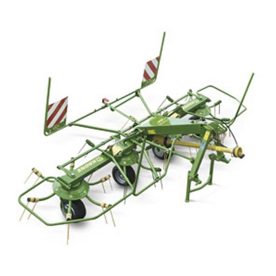
- Page 1 Operating instructions Nr. 114-4 GB Rotary tedder KW 5.50 / 4 x 7 KW 6.70 / 6 (from machine no. 455 090) KW 7.70 / 6 x 7 KW 8.80 / 8...
- Page 2 (Dr. Josef Horstmann, Engineering Group Director) (Josef Jungehüser, Director of Quality Control) Dear customer, You have now received an operating manual for the KRONE product which you have purchased. This operating manual contains important information for the pro- per use and safe operation of the machine.
-
Page 3: I Foreword
Read these operating instructions carefully before you Maschinenfabrik Bernard Krone GmbH use the machine, and pay special attention to the Heinrich-Krone-Straße 10, D 48480 Spelle safety instructions. Jahr Masch. Nr Année No. -
Page 4: Table Of Contents
List of contents Foreword........................... 1 List of contents ........................ 2 General ..........................3 Introduction Position of the warning signs, with safety-technical information, on the machine .... 6 Position of the general information labels on the machine..........8 Technical data ........................10 Preparations for use Special safety instructions .................... -
Page 5: General
III. General 1. Operation in Accordance with 5. The operator´s clothing should be tight fitting. Avoid wearing loose fitting clothes. Specifications 6. Keep the machine clean to prevent the danger of fire! The rotary tedder is designed solely for normal agricultural use (operation in accordance with specifications). - Page 6 22.Persons are not allowed to enter the working area! 5.When using P.T.O. shafts with overload or free wheel clutches that are not covered by the guards on the 23.Keep clear of the area of rotation and swing of the tractor, the overload or free wheel clutches must be equipment! fixed on the implement side! 24.Hydraulic controls must only be operated if no persons...
- Page 7 Danger of infection! technical requirements defined by the manufacturer! 8. Before carrying out any work on the hydraulic The best guarantee is to use only original KRONE parts! systems, lower the machine to the ground, depressurize the system and turn off the engine! 10.Where gases are stored, only refill with nitrogen.
-
Page 8: Introduction
Introduction The KRONE rotary tedder is equipped with all necessary safety features (protective devices). Not all danger points on this machine can be completely secured with regard to the preserving of the function of the machine. The machine bears appropriate warning labels to point out these residual dangers. - Page 9 939 100-4 540/ MAX. Read and take note of the MAX. operating manual. Do not exceed the maximum permitted PTO shaft speed! Order No. 939 100-4 (1x) Order No. 939 471-1 (1x) No personnel allowed inside swivel space of Danger from self-turning swather disk arms. the operating equipment while the deployment Maintain safe distance! arms are being folded down.
-
Page 10: Position Of The General Information Labels On The Machine
Location of General Information Labels on the Machine KZW-1-001... - Page 11 942 295-0 500 lang 942 296-0 370 lang 942 297-0 200 lang grün 440 135-3 (1x) bei KW 5.50 942 298-0 200 lang beige 939 429-2 (1x) bei KW 6.70 440 148-2 (1x) bei KW 7.70 942 103-1 (1x) 942 273-1 (1x) bei KW 8.80 72 Nm 85 Nm 42 Nm...
-
Page 12: Technical Data
1.3 Technical data Type KW 550/4x7 KW 670/6 KW 770/6x7 KW 880/8 Working width [mm] 5500 6700 7700 8800 Number of swather discs Tine arms per swather disc Surface covered [appr. ha/hr] Width in transport position [mm] 2930 2950 2980 2980 Height in transport position [mm] 2800... -
Page 13: Preparations For Use
2. Preparations for use 2.1. Special safety instructions • In all care, maintenance, repair and assembly work on the rotary tedder the PTO shaft must always be switched off. Switch off the engine and remove the ignition key. Take measures to prevent the tractor and rotary tedder from rolling! •... -
Page 14: Attaching The Rotary Tedder To The Tractor
Mounting the PTO shaft on the rotary tedder KW 5.50 / 4x7 and KW 6.70 / 6 Only those PTO shafts provided may be mounted and used. To mount the PTO shaft on the rotary tedder, unscrew the screw (1) on the rotary shaft protective sleeve (2), twist the protective socket and the protective tube against each other and push the PTO shaft protective sleeve in the direction of the arrow. - Page 15 KW-0-010 KW 5.50/4x7; KW 6.70/6 and KW 7.70/6x7 Take the hydraulic switchover valve (1) out of the bracket (4) and insert it into the holder on the tractor. Take the hydraulic hose (2) out of the bracket (3) and insert it into the coupling of a single action control valve.
- Page 16 KW 8.80/8 The swather disk arms are secured in transport position with hydraulic stop valves on the hydraulic cylinders. In cases of transport journeys, the shut-off valve (1) must be closed and the tractor control valve must be locked! KW-4-001 Before raising the rear hydraulics, make sure that the rear window of the tractor cabin is closed.
-
Page 17: Adapting The Pto Shaft Length
2.4 Adjusting the PTO shaft length • Risk of damage to material. Do not raise the rotary tedder before the length of the PTO shaft has been adapted! • The PTO shaft must be switched off before any, maintenance, repair and assembly work is carried out on the rotary tedder. -
Page 18: Working Position
Only for KW 7.70/6x7 and KW 8.80/8 Move the undercarriage wheel (2) on the second swather disk forward into working position. Secure with the bolt (1) and linch pin. -
Page 19: Transport Position
(1). Lift the outer swather discs by operating the tractor hydraulic system. KW-0-049 KW 5.50/4x7; KW 6.70/6 and KW 7.70/6x7 Raise the outer swather discs until the locking devices (1) have fully clicked into place. Be sure that the transport locking device has correctly engaged and that the control cable is not taut. -
Page 20: Disassembly Of The Rotary Tedder
Only for KW 7.70/6x7 and KW 8.80/8 CAUTION: Observe the maximum width of the machine when travelling on public roads. For reducing the transport width (< 3 m): • Lower the undercarriage wheel (3) on the second wather disk backwards into transport position •... - Page 21 Depressurize the hydraulic system before pulling off the hydraulic hoses. • Pull off the hydraulic hose (2). (one hydraulic hose for KW 5.50/4x7, KW 6.70/6 and KW 7.70/6x7; two hydraulic hoses for KW 8.80/8) • Take the hydraulic switchover valve (1) from the bracket on the tractor and place it in the corresponding bracket (4) on the rotary tedder.
-
Page 22: Settings
3. Settings 3.1 Special safety instructions • The adjustments described here must only be carried out when the machine is at a complete standstill. Switch off the engine and remove the ignition key. • Secure the rotary tedder and tractor from rolling. -
Page 23: Adapting The Swather Discs To The Ground
(The cylinder must not however come into contact with the tow bar.) KW-4-004 Outer swather disc of KW 6.70/6 and KW 7.70/6x7 The outer swather discs of the KW 6.70 and KW 7.70 can be adapted to the ground conditions. •... -
Page 24: Edge Spreading Mechanism
3.5 Edge spreading mechanism The undercarriage wheel setting can be seen on the pointer (1). It is situated to the right of the carrier bar in forward direction. KW-0-035 To adjust the edge spreading mechanism, raise the rotary tredder. Switch the hydraulic switchover valve (1) to position "b"... -
Page 25: Tine Adjustment
3.7 Tine adjustment The tines (3) must be aligned vertically to the ground. The alignment of the tines can be changed by turning the eccentric. For adjustment release securing bolt (1) and turn eccentric (2) to the next position. Tighten the adjustment screw to a torque setting of 95 Nm. -
Page 26: Care And Maintenance
4. Care and maintenance 4.1 Special safety instructions • Repair, service, maintenance and cleaning work must only be carried out when the machine is at a standstill. Switch off the engine and remove the ignition key. • Protect the rotary tedder and tractor from rolling. •... -
Page 27: Hydraulics
4.3 Hydraulics The rotary tedder has a hydraulic cylinder with an integrated hydraulic accumulator (1) in the edge spreading mechanism. The system is maintenance- free. The cylinder unit is under pressure. If a defect occurs, the complete unit must be replaced. Hose lines are subject to ageing. - Page 28 Lubrication points on the KW 5.50 / 4x7...
- Page 29 Lubrication points on the KW 6.70 / 6 and KW 7.70 / 6x7...
- Page 30 Lubrication points on the KW 8.80 / 8 For reasons of clarity, the lubrication points have been shown on only one side of the rotary tedder. On the other side, there are lubrication nipples at exactly the same points (as a mirror image).
-
Page 31: Winter Storage
Have necessary repair work carried out in the period directly after the harvest season. Make up a collective list of all replacement parts required. This will make it easier for your KRONE dealer to deal with your orders, and it will give you the security of knowing that your machine will be fully operational at the beginning of the new season. -
Page 32: Special Accessories
7. Special accessories 7.1 Night swathing gearbox The rotary tedder can be equipped with a night swathing gearbox. The following parts are supplied: - Night swathing gearbox (1) (maintenance-free due to permanent grease filling) - Two angle brackets (2) - Protecting pot (3) - Clamp fitting (4) - Four bolts with nuts and washers KW-0-027... -
Page 33: Additional Tine Loss Safety Mechanism
The PTO shaft stup (1) is designed for spreading and tedding. To lay night swathes, push the PTO shaft onto stup (2). As the swathes are deposited by the same swather discs that are used for tedding, ideal spreading is assured after the swathing process. -
Page 34: Wheel Guards
7.3 Wheel guards • For all service, maintenance, repair and assembly work on the rotary tedder, always switch off the PTO shaft. • Switch off the engine and remove the ignition key. • Protect the tractor and rotary tedder from rolling! •... - Page 35 Fit the wheel guard (1) from above onto the wheel bracket (4). The bolt (3) must lie on the wheel bracket. Mount the distance plate (5) between the wheel bracket and the wheel guard. Put the screw-on clip (6) in place and screw it tight.
-
Page 36: Fixed Lighting
7.4 Fixed lighting A permanently fixed lighting system can be mounted on all rotary tedders. To fit the system, unscrew the brack- ets for fitting the removeable lights on the warning signs (1). In the middle of the square warning signs and at the lower end of the oblong warning signs there is a hole (3) through which the supply cable to the lamps (2) can be passed. -
Page 37: Appendix To The Operating Manual (Assembly Instructions)
Appendix to the Operating Instructions Assembly instructions for the KW 5.50 / 4x7, KW 6.70 / 6, KW 7.70 / 6x7 and KW 8.80 / 8 The work described on the following pages must only be carried out by authorized specialist dealers. Because safety devices must be mounted as well, the rotary tedder cannot be put into operation until all the tasks described below have been completely carried out. - Page 38 1. Special safety instructions • Place the rotary tedder on a firm, level surface. • Before starting the rotary tedder, fit all safety equipment. • When folding the outer discs to working position, make sure that nobody is in the swivel area of the discs.
- Page 39 5. Mounting the protective frames 5.1 Mounting the protective frames to the KW 5.50/4x7 Side protective frames to right and left: The side protective frames (1) are fixed to the bar (3) with an angled bracket (2). Detach the angled bracket from the protective frame and bar.
- Page 40 Bolt the front protective frame (2) into place in position "1" to the left and right of the carrier bar and in position "3" below the carrier bar. KW-0-043 After mounting the front protective frame, fix the stabilizer (1) to the holding bracket (4) of the protective frame with bolts (3) and secure it with a roll pin.
- Page 41 5.2 Mounting the protective frames to KW 6.70 / 6 and KW 7.70 / 6x7 KW-4-003 Protective frames "a" and "b" are mounted in the factory. Mounting of the protective frames "c = front protective frames" and "d = rear protective frames" is carried out as described for the KW 5.50 / 4x7 (see 5.1).
- Page 42 5.3 Mounting of the protective frames to the KW 8.80 / 8 KW-4-005 Protective frames "a" and "b" are mounted in the factory. Mounting of the protective frames "c = front protective frames" and "d = rear protective frames" is carried out as described for the KW 5.50 / 4x7 (see 5.1).
- Page 43 5.4 Mounting the warning signs KW 5.50/4x7 The warning signs (1) are fitted from below to the front and rear protective frames (3) and fixed in place with two bolts (2) that are inserted right through. KW-0-065 Light brackets for removeable lights The illustration shows the mounting positions of the front light brackets (1) and (4) and the rear light brackets (2) and (3) on the warning signs.
- Page 44 KW 6.70/6, KW 7.70/6x7 and KW 8.80/8 Install the lighting brackets before fitting the front warning panels. Anzahl Pos. Maße M 8 x 20 8.4 x 17 x 4 Anzahl Pos. Maße Always mount the warning signs so that the stripes are pointing...
- Page 46 . . konsequent, kompetent Maschinenfabrik Bernard Krone GmbH Heinrich-Krone-Straße 10, D-48480 Spelle Postfach 11 63, D-48478 Spelle Phone +049 (0) 59 77/935-0 +049 (0) 59 77/935-339 Internet: http://www.krone.de eMail: info.ldm@krone.de...
Need help?
Do you have a question about the KW 7.70/6x7 and is the answer not in the manual?
Questions and answers