
Related Manuals for IFM OY Series


Summary of Contents for IFM OY Series
- Page 1 Original operating instructions Photoelectric safety sensors (safety light curtain) for finger protection (resolution / detection capacity 14 mm)
-
Page 2: Table Of Contents
Contents 1 Preliminary note ���������������������������������������������������������������������������������������������������4 1�1 Symbols used ������������������������������������������������������������������������������������������������4 1�2 Warning signs used ���������������������������������������������������������������������������������������4 2 Safety instructions �����������������������������������������������������������������������������������������������5 2�1 Safety-related requirements regarding the application ����������������������������������6 3 Items supplied������������������������������������������������������������������������������������������������������7 4 Functions and features ����������������������������������������������������������������������������������������7 5 Function ���������������������������������������������������������������������������������������������������������������8 6 Installation������������������������������������������������������������������������������������������������������������9 6�1 Installation instructions ����������������������������������������������������������������������������������9 6�2 Calculation of the minimum safety distance ������������������������������������������������10 6�3 Vertical installation of the safety light curtains ���������������������������������������������12 6�3�1 Safety light curtains resolution 14 mm ������������������������������������������������12... - Page 3 10�1�2 The switched state ����������������������������������������������������������������������������25 10�1�3 Interface classification ����������������������������������������������������������������������25 10�2 Functional test of the safety light curtains �������������������������������������������������26 11 Scale drawing ��������������������������������������������������������������������������������������������������27 12 Technical data ��������������������������������������������������������������������������������������������������28 12�1 Safety light curtains: 14 mm resolution ������������������������������������������������������29 13 Troubleshooting �����������������������������������������������������������������������������������������������29 13�1 Fault diagnosis transmitter ������������������������������������������������������������������������29 13�2 Fault diagnosis receiver �����������������������������������������������������������������������������30 14 Maintenance, repair and disposal ��������������������������������������������������������������������31 15 Terms and abbreviations ����������������������������������������������������������������������������������32...
-
Page 4: Preliminary Note
1 Preliminary note The instructions are part of the unit� They are intended for authorised persons according to the EMC and low voltage directives and safety regulations� The instructions contain information about the correct handling of the product� Read the instructions before use to familiarise yourself with operating conditions, installation and operation�... -
Page 5: Safety Instructions
2 Safety instructions • Follow the operating instructions� • In case of non-observance of notes or standards, specially when tampering with and/or modifying the unit, any liability and warranty is excluded� • The unit must be installed, connected and put into operation by a qualified electrician trained in safety technology�... -
Page 6: 2�1 Safety-Related Requirements Regarding The Application
► For applications in the food industry contact your ifm branch office to check the compatibility of the materials of the photoelectric safety sensors with the chemicals used�... -
Page 7: Items Supplied
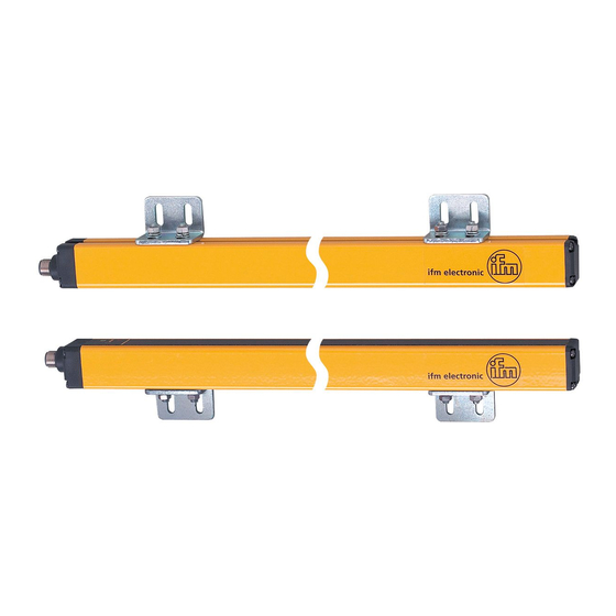
• 1 copy operating instructions photoelectric safety sensors, reference no� 704701� If one of the above-mentioned components is missing or damaged, please contact one of the ifm branch offices� 4 Functions and features transmitter (T) receiver (R) P = protected area;... -
Page 8: Function
5 Function The protected area (P) is generated between the transmitter and the receiver and is defined by the protected area height (H) and the protected area width (range) (I)� The protected area height is the height protected by the safety light curtain� It depends on the design (→... -
Page 9: Installation
6 Installation 6.1 Installation instructions The following conditions are to be ensured before installation of the photoelectric safety sensors: • The degree of protection of the electro-sensitive equipment (ESPE) has to correspond with the risk assessment of the machine to be monitored� •... -
Page 10: 6�2 Calculation Of The Minimum Safety Distance
Observe the following illustrations for correct installation of the photoelectric safety sensors� Correct installation Wrong installation 6.2 Calculation of the minimum safety distance There must be minimum safety distance between the photoelectric safety sensor and the point of danger� This distance must be ensured so that the point of danger cannot be accessed before the hazardous state of the machine has been stopped�... - Page 11 ► Install the photoelectric safety sensor at a distance that is greater or equal to the minimum safety distance (S) so that the hazardous area (A) can only be accessed after complete standstill of the hazardous machine motion� According to the European Standard EN 999:2008 the following formula is to be used to calculate the minimum safety distance (S): S = K (t1 + t2) + C...
-
Page 12: 6�3 Vertical Installation Of The Safety Light Curtains
6.3 Vertical installation of the safety light curtains 6.3.1 Safety light curtains resolution 14 mm These designs are suitable for access prevention of fingers (finger protection)� The minimum safety distance (S) is determined using the following formula: S = 2000 (t ) + 8 (d - 14) This formula applies to minimum safety distances (S) between 100 and 500 mm�... -
Page 13: 6�4 Fixing And Optical Alignment
6.4 Fixing and optical alignment Correct alignment of the transmitter and the receiver is decisive for the proper function of the photoelectric safety sensors� ► Install the transmitter and the receiver using the supplied mounting accessories so that they are exactly opposite each other� ►... -
Page 14: 6�4�1 Optical Alignment
6.4.1 Optical alignment T = transmitter; R = receiver The indication LEDs of the receiver help to correctly align the photoelectric safety sensors� Receiver 2-colour LED 2-colour LED Description green yellow blue Receiver does not detect any light beams Receiver detects some light beams Receiver detects all light beams with a weak signal Receiver detects all light beams... -
Page 15: 6�5 Distance Of The Reflecting Surfaces
6.5 Distance of the reflecting surfaces Reflective surfaces close to photoelectric safety sensors can disable the safety function of the system� The minimum distance (D) depends on the protective area width (I) taking into consideration the projection and receiving angles� The minimum distance (D) between reflective surfaces and the protected area (P) must be observed�... - Page 16 Minimum distance to reflective surfaces 1100 1000 D = minimum distance in [mm]; I = protected area width (range) [m]...
-
Page 17: 6�6 Multiple Systems
6.6 Multiple systems The use of several safety light curtains can lead to malfunction and disable the protective function� The safety light curtains are to be installed so that the beam sent by the transmitter of a system can only be detected by the respective receiver� The following important rules for installation are to be observed to avoid mutual interference of several systems: Arrangement A... -
Page 18: 6�7 Use Of Corner Mirrors
6.7 Use of corner mirrors To protect and monitor hazardous areas with access from several sides one or several mirrors can be used (available as accessory)� By using mirrors the light beam emitted by the transmitter can be sent via several access sides� ►... -
Page 19: Electrical Connection
Range 1 Configuration protected area width Functional earth For information about available sockets/connectors see: www.ifm.com → Products → Accessories The protected area width (range) to be used is configured via range 0 and range 1� Configuration protected area width (range) -
Page 20: 7�2 Wiring Diagram Receiver
– Functional earth For information about available sockets/connectors see: www.ifm.com → Products → Accessories Note: Lay the cables of the photoelectric safety sensors separately from sources of interference such as power lines� ► Connect the transmitter and the receiver to the functional earth�... -
Page 21: Operating Modes
8 Operating modes The different operating modes of the safety light curtains of the OY series can be set via the respective connections to the 8-pole plug of the receiver� Operating modes Connections pin 4 pin 5 pin 6 Automatic... -
Page 22: 8�1 Automatic Operation
8.1 Automatic operation If the safety light curtains are used in the automatic mode, monitored start is not possible� The safety light curtains automatically return to operation with clear protected area, the outputs (OSSDs) are activated� Verify if this is compatible with your machine� In the automatic mode the OSSD1 and OSSD2 outputs follow the status of the safety light curtains: Protected area clear... -
Page 23: 8�3 Connection Of External Contactors
8.3 Connection of external contactors External contactors can be integrated in the automatic or manual operating mode� The contactors have to be connected in series between the supply voltage and pin 4 of the receiver (→ 8 Operating modes / table, fig. B ). With manual function a start button has additionally to be switched in series (→... -
Page 24: 9�1 Led States
9.1 LED states The blue LED is lit when the signal is weak (→ 6.5.1 Optical alignment). transmitter receiver Description green orange green yellow blue Activating the system, input test Fault (→ 13 Troubleshooting) Test condition Normal operating conditions Protected area interrupted, outputs deactivated Protected area clear, outputs deactivated,... -
Page 25: 10�1�1 The Safe State
10.1.1 The safe state The safe state is when the output is switched off (zero-current state: logic "0") of min� one of the outputs (OSSDs)� If one of the outputs is switched off, the subsequent safety-related logic unit must bring the complete system into the state defined as safe� 10.1.2 The switched state In switched state the receiver provides a current of 24 V DC (logic "1") to both outputs�... -
Page 26: 10�2 Functional Test Of The Safety Light Curtains
For information about available test rods see: www.ifm.com → Products → Accessories. ► Let the test object enter the protected area and move it slightly downwards� First of all in the centre and then close to the transmitter and the receiver�... -
Page 27: Scale Drawing
11 Scale drawing 14,5 10,5 M12x1 transmitter 1: LED 3 colours (red/green/orange) receiver 2: LED 2 colours (yellow/blue) total length* 3: LED 2 colours (red/green) * available lengths → 12 Technical data... -
Page 28: Technical Data
12 Technical data Conforms to the requirements of: Type 4 IEC 61496-1, SIL 3 IEC 61508, SILcl 3 IEC 62061, ISO 13849-1:2015 category 4 PL e Electrical design DC / PNP Operating voltage 24 DC (19�2…28�8) Current consumption Transmitter [mA] 42 Receiver [mA] 83 Outputs (OSSDs) -
Page 29: 12�1 Safety Light Curtains: 14 Mm Resolution
(→ 9 Operating and display elements). For a detailed fault description see the following tables� 13.1 Fault diagnosis transmitter Possible cause Troubleshooting 2 consecutive Faulty connection Check connections pins 2 and 4 pulses pin 2/4 3/4 consecutive Internal fault Send device to ifm branch office for repair� pulses... -
Page 30: 13�2 Fault Diagnosis Receiver
5 consecutive Fault Check connections� pulses OSSD outputs If the defect remains, send device to ifm branch for repair� 6/7 consecutive Internal fault Send device to ifm branch office for pulses repair� yellow... -
Page 31: Maintenance, Repair And Disposal
14 Maintenance, repair and disposal • Maintain the optoelectronic protective equipment in accordance with the applicable national regulations in effect within the requested intervals� The tests must be performed by qualified persons� • It is recommended to regularly clean the front panes of the transmitter and the receiver�... -
Page 32: Terms And Abbreviations
Safety integrity level SIL 1-4 to IEC 61508� The higher the SIL the lower the probability that a safety function will fail� Safety integrity level (to IEC 62061) claim limit Mission Time Technical data and further information at www�ifm�com... -
Page 33: Annex
16 Annex 16.1 Check list This check list serves as help for setting up the safety light curtains� The requirements in this check list should to be met, however depending on the application and the directives / standards referred to� 1�...
Need help?
Do you have a question about the OY Series and is the answer not in the manual?
Questions and answers