Cattron CANplus CP1000 Operation Manual
Hide thumbs
Also See for CANplus CP1000:
- Installation manual (15 pages) ,
- Operation manual (46 pages) ,
- Operation manual (72 pages)
Table of Contents
Advertisement
Quick Links
Advertisement
Table of Contents

Related Manuals for Cattron CANplus CP1000


Summary of Contents for Cattron CANplus CP1000
- Page 1 ™ CANplus CP1000 & CP1000BLE Control Panel Operation Manual 9M02-1000-A401-EN...
- Page 2 Cattron makes no warranties as to non-infringement nor as to the fitness, merchantability, or sustainability of any Cattron products for any specific or general uses. Cattron Holdings, Inc., or any of its affiliates or agents shall not be liable for incidental or consequential damages of any kind.
-
Page 3: Table Of Contents
CANplus CP1000 Control Panel Operation Manual IMPORTANT SAFETY AND EMISSIONS INFORMATION ................5 ..........................5 AFETY OTATION ........................... 5 AFETY NSTRUCTIONS ...................... 7 UXILIARY NGINE ISCLAIMER ..................7 XHAUST MISSIONS OMPLIANCE ISCLAIMER OVERVIEW..............................8 DISPLAY ..............................9 ............................9 UTTON ............................. - Page 4 CANplus CP1000 Control Panel Operation Manual ............................31 CHEDULER ............................31 IMED ........................32 ATTERY ECHARGE ..........................32 NTIFREEZE CANPLUS CONTROL ..........................33 .......................... 33 YNAMIC HROTTLING ........................... 33 AUSE AT UN SPEED ......................33 HROTTLE BY AINTAIN OINT ..........................33 ONTROLLED ..........................
-
Page 5: Important Safety And Emissions Information
CANplus CP1000 Control Panel Operation Manual 11.3.6 Welding on Equipment with Electronic Controls ................44 11.4 C ....................45 ONTROL YSTEM ROUBLESHOOTING 11.4.1 Testing a Warning or Shutdown ....................45 11.4.2 Testing CAN ..........................45 11.5 D (DTC) ..................... 46... - Page 6 CANplus CP1000 Control Panel Operation Manual CAUTION THIS DOCUMENT MUST BE COMPLETELY READ AND UNDERSTOOD PRIOR TO INSTALLING, TESTING OR OPERATING THE EQUIPMENT DESCRIBED WITHIN. FURTHER, THIS DOCUMENT MUST BE RETAINED FOR CURRENT AND FUTURE USERS OF THIS EQUIPMENT. FAILURE TO...
-
Page 7: Auxiliary Engine Stop Disclaimer
CANplus CP1000 Control Panel Operation Manual CAUTION THE INSTALLER OF THIS CANPLUS PANEL AND/OR CANPLUS HARNESS IS RESPONSIBLE FOR THE CORRECT SIZING AND INTEGRATION OF A SUITABLE FUSE/BREAKER ON THE UNSWITCHED DC CIRCUIT SUPPLYING POWER TO THE CANPLUS PANEL. CAUTION ONLY TRAINED AND QUALIFIED PERSONS MAY PERFORM INSTALLATION, TESTING, SERVICE OR REPAIR WORK ON THE CANPLUS PRODUCT. -
Page 8: Overview
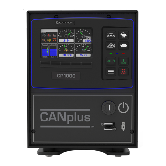
ECU initiated emissions event. Overview The CANplus CP1000 control panel is a manual and auto-start platform for EPA Tier 3, EPA Tier 4 (interim), EPA Tier 4 and EU Stage V electronically governed diesel or natural gas engines. It can also control mechanically governed diesel engines. -
Page 9: Display
CANplus CP1000 Control Panel Operation Manual Display The CANplus display is a robust, sunlight-viewable 4.3” WQVGA color display with five integrated backlit display buttons and eight large control buttons housed in a rugged, water-tight IP66 rated enclosure. The five display keys simplify and enhance the user interface by providing positive tactile feedback when pressed. -
Page 10: Gauge
CANplus CP1000 Control Panel Operation Manual Gauge Pages There are four independently configurable pages of analog gauges. To change Gauge Pages, press any of the first four buttons to show the top-level button bar and then press button 1 to cycle through the pages. The current page is indicated by the number in the center of the screen, as shown below. -
Page 11: Autostart And Throttling Dashboards
CANplus CP1000 Control Panel Operation Manual Autostart and Throttling Dashboards 3.4.1 Autostart Click here to view the Autostart dashboard video. When the Dashboard-1 button is pressed, the display will change to the full screen Autostart dashboard, as shown below. When the Dashboard-1 button is pressed again, the display will revert to the gauge page. -
Page 12: Active Alarms
CANplus CP1000 Control Panel Operation Manual Pressing the Dashboard-2 button again will cause the display to revert to the gauge page. Active Alarms When an active alarm is received, a flashing popup window is overlaid on the current screen. The popup includes a plain language description in addition to the standard SPN/FMI (Suspect Parameter Number/Failure Mode Indicator) pair defined by the SAE J1939 standard. -
Page 13: Service Timers
Equipment Fault Code Diagnostic Information system (additional information is available at www.cattron.com/resources/cattron-patents). Pressing this button again displays a QR-code specific to this alarm. The QR-code can be scanned using the camera on most smart phones. When scanned, the phone will give an option to automatically jump to the RemoteIQ™... -
Page 14: Menus
CANplus CP1000 Control Panel Operation Manual Menus The menu pages can be accessed by pressing button 5. The top-level menu page will then appear. From there the functions of the five display buttons change to allow navigation and selecting and modifying parameters. - Page 15 CANplus CP1000 Control Panel Operation Manual Distance Pressure Volume Temperature Gauges • – Quadrant Page 1-4 Top Left Top Right Bottom Left Bottom Right Power Timeout • System Setup • Configurations & Updates • Restore Defaults Set Date & Time •...
- Page 16 CANplus CP1000 Control Panel Operation Manual Tachometer Engine Hours Coolant Temp Oil Pressure – Yanmar – CAT / Perkins • About • Logging Manufacturer Info • Import License • License Viewer • Emission Control • Request Force Regen Inhibit Regen Disable/Enable •...
- Page 17 CANplus CP1000 Control Panel Operation Manual · High → Low Auto Throttle Input Transducer 1,2,3,4,5,6 · Target Point Throttle Aggressiveness Error Operation · Controlled Stop, Immediate Stop, Go to Run, Derate Ramp Profile • – RPM Settings Intermediate RPM Run RPM –...
- Page 18 CANplus CP1000 Control Panel Operation Manual • Auto Battery Recharge – Auto Battery Enabled Off/On – Recharge Run Speed – Enable Delay (m) – Recharge Time (m) – Delay Between Recharge (m) – Low Battery Threshold (V) Auto Antifreeze •...
-
Page 19: Access Levels
CANplus CP1000 Control Panel Operation Manual LED Select Red, Amber · LED Flash Rate Slow, Fast, Solid · Communications • CAN bus Settings – TSC1 Address – Panel Address – CM1 Address – Interlock Address – Config Address – Termination Modbus •... -
Page 20: Quick Access Menu
CANplus CP1000 Control Panel Operation Manual displayed, and the access level reverts to User. Once elevated, the access level stays in effect until the panel is turned off or the display times out (see display Power Timeout). PIN Change PINs can be changed via the Menu as follows: Configuration → System → PIN Settings → PIN change . -
Page 21: Engine Or Vfd Setup
VFD model from the list. If the VFD being used is not listed, contact Cattron Sales to request the addition. In this same menu, verify that the Tri-Vib sensor and VFD addresses are different. The final step in this menu, is to verify the Modbus parity, baud rate, & stop bit match System →... -
Page 22: Mechanically Governed Engines
CANplus CP1000 Control Panel Operation Manual Mechanically Governed Engines All of the following panel menu actions described in this section require Admin-level privileges. System → Engine Type To configure the panel for a mechanical engine, first go to the menu and select the System →... -
Page 23: Ramp Throttle
CANplus CP1000 Control Panel Operation Manual For example, the panel’s Minimum Requested RPM is set to 800 RPM, yet the ECU payload defines the engine minimum speed to be 900 RPM. In this case, the engine will not run at 800 RPM despite the control panel requesting a lower engine speed. -
Page 24: Autostart Operation
CANplus CP1000 Control Panel Operation Manual Autostart Operation Prerequisites The CP1000 is capable of starting and stopping the engine or motor based on external triggers and/or timed schedules. Note: It is important to note that the engine or motor may start without warning or notice. -
Page 25: Configuring Operation
CANplus CP1000 Control Panel Operation Manual Click here to view Transducer with Backup Switches. 6.4.1 Configuring Operation Configuring Autostart begins with selecting the desired behavior. The two choices are as follows: 1. High to low, examples: High water level to low water level •... - Page 26 CANplus CP1000 Control Panel Operation Manual Start/Stop Events Engine or Motor Starts When Engine or Motor Stops When Transducer with Backup Input is above high set point; Dual Input is below low set point; Dual Switch mode if Transducer fault is...
-
Page 27: Configuring The Transducer
CANplus CP1000 Control Panel Operation Manual Faults Transducer Level Low-Level Switch High-Level Switch Result Transducer is within normal Above Low-Level Point Open — operating range, but value is incorrect (too high) because low- level float should be closed Below High-Level Point —... -
Page 28: Configuring Start And Stop Delays
CANplus CP1000 Control Panel Operation Manual The following figure demonstrates the responsiveness of a system to adjustments in Throttle Aggressiveness. A fast-responding system will need a lower aggressiveness value. Otherwise, the RPMs will overshoot and undershoot the target value as depicted in the graph by the red “Too High” throttle aggressiveness line. Ideally, the RPM should quickly ramp up and home in on a small RPM range to maintain the target value as depicted in the graph by the green “Correct”... -
Page 29: Ramp Profile
CANplus CP1000 Control Panel Operation Manual 6.4.5 Ramp Profile The Auto ramp profile allows the use of configurable warm up and cool down profiles to help protect the equipment and other assets such as plumbing, or to ensure proper ramp up and down of pressure or flow. An example is shown below. -
Page 30: Configuring Rpm And Time Profile Settings
CANplus CP1000 Control Panel Operation Manual 6.4.6 Configuring RPM and Time Profile Settings Setting Description Idle RPM Selects the RPM that the control system will request for idle speed. If the engine or motor is started, it will always begin running at Idle speed. -
Page 31: Scheduler
CANplus CP1000 Control Panel Operation Manual • Type and Range – 4 mA Scaled Value Value in setup units represented by a 4-mA reading – 20 mA Scaled Value Value in setup units represented by a 20-mA reading – Setup Units Units used to setup the 4 mA and 20 mA scaled values –... -
Page 32: Auto Battery Recharge
CANplus CP1000 Control Panel Operation Manual Auto Battery Recharge The CP1000 can be configured to monitor the battery and crank up the engine to recharge the battery once the battery voltage falls to a configured level. To enable and configure this feature with Tech or Admin level access, Autostart→... -
Page 33: Canplus Control
Control Panel Operation Manual CANplus Control The CP1000 has expanded throttle capabilities, which provides users with more options to control electronically governed engines, electrical motors, or mechanically governed engines when equipped with the Cattron Throttle Actuator. CANplus Control Throttling Options: Dynamic Throttling* •... -
Page 34: Auto/Manual Mode Toggle
CANplus CP1000 Control Panel Operation Manual Click for a video showing Setup and Demonstration or go to here https://youtu.be/3HILfk1TSV8 Auto/Manual mode Toggle Auto/Manual Mode Toggle allows switching between modes without shutdown the engine or motor Momentary Rabbit/Turtle Keys Momentary Rabbit/Turtle Keys Throttle adjustment via momentary rocker switch... -
Page 35: Configuration And Manufacturing Info
CANplus Customizer Software Suite, which is proprietary configuration software, is highly recommended. The software suite is meticulously maintained and regularly updated. These free updates include software enhancements and new functionality, and they ensure compatibility with evolving technologies. Please see the Resources section at www.cattron.com/cp1000. *Patent Pending 9M02-1000-A401-EN... -
Page 36: Can Plus Customizer Software Suite And Ausb Drive
CANplus CP1000 Control Panel Operation Manual The CANplus Config Kit (Part Number 010-6750-01) includes the following: • An adapter harness that connects to the panel’s engine interface connector • An AC power supply • A USB to CAN bus hardware adapter With this kit, a panel’s configuration can be read from the panel or written to the panel via CAN bus. -
Page 37: Loading A Saved Configuration To Be The Operational Configuration
CANplus CP1000 Control Panel Operation Manual 9.4.2 Loading a Saved Configuration to be the Operational configuration System → Saved To make a saved configuration be the operational configuration, navigate to Configurations. Use the display buttons to select the desired file. Pressing the middle display button will make that configuration the panel’s operational configuration. -
Page 38: Viewing The Manufacturer Info
CANplus CP1000 Control Panel Operation Manual 9.5.3 Viewing the Manufacturer Info System → The stored Manufacturer Info can be displayed with all access levels by navigating to Manufacturer Info *Patent Pending 9M02-1000-A401-EN Revision G... -
Page 39: Firmware Update
CANplus CP1000 Control Panel Operation Manual Firmware Update The CP1000 utilizes a USB drive and its USB front USB port to update the application firmware. 10.1 Updating via USB Drive 10.1.1 Preparation Copy the update file into the root directory of an empty USB stick, which has been formatted with FAT32. -
Page 40: Miscellaneous
CANplus CP1000 Control Panel Operation Manual Miscellaneous 11.1 Emissions System Functionality Note: GENERAL EMISSIONS DISCLAIMER This panel may include provision(s) for operator input such as FORCE REGENERATION, INHIBIT REGENERATION, INTERLOCK, and others specific to US and International emissions regulations. Responsibility for emissions-related inputs and compliance with emissions regulations is solely that of the owner and/or operator of the machine/engine or motor on which this panel is connected. -
Page 41: Typical J1939 Wiring Topology
CANplus CP1000 Control Panel Operation Manual 11.2.1 Typical J1939 Wiring Topology 11.2.2 Engine Harness Connector Connection to the engine is provided by a Deutsch/TE 21 pin connector (Part Number HDP24-24-21PE). The mating connector is Deutsch/TE (Part Number HDP26-24-21SE). Signals are shown in Table 1. -
Page 42: Sealed Connectors
USE CATTRON PROVIDED CAVITY PLUGS TO SEAL THE CONNECTOR IF WIRES ARE REMOVED. 11.2.4 Unsealed Connectors For unsealed connectors exposed to the elements, Cattron recommends using dielectric grease to protect the contacts. CAUTION CATTRON DOES NOT RECOMMEND USING SEALANT WITH UNSEALED CONNECTORS. -
Page 43: Battery Circuit Requirements
Maximum Starter Relay Excitation Current Draw 5 A @ 12 V 3 A @ 24 V Cattron provides suitable heavy-duty relays and generic starter relay wiring kits in both 12 V and 24 V; please contact your LOFA reseller for more information. -
Page 44: Suppression Of Voltage Transients (Spikes)
11.3.5 Suppression of Voltage Transients (Spikes) CAUTION THE INSTALLATION OF VOLTAGE TRANSIENT SUPPRESSION AT THE TRANSIENT SOURCE IS REQUIRED. CATTRON FOLLOWS SAE RECOMMENDED ELECTRICAL ENVIRONMENT PRACTICES. Inductive devices such as relays, solenoids and motors generate voltage transients and noise in electrical circuits. -
Page 45: Control System Troubleshooting
CANplus CP1000 Control Panel Operation Manual 11.4 Control System Troubleshooting Control system does not perform self-test Possible Cause Possible Remedy Tripped overcurrent protection Correct fault, replace or reset overcurrent protection Faulty connection to battery Correct battery connections (see the Battery Circuit Requirements... -
Page 46: Diagnostic Trouble Codes (Dtc)
CANplus CP1000 Control Panel Operation Manual 1. Disconnect the battery and the panel 2. Connect an ohmmeter across the green and yellow CAN pins (pins u & v) of the D21 connector. 3. A reading of near 0 ohms indicates the other end of the bus is not correctly terminated or not intact. - Page 47 CANplus CP1000 Control Panel Operation Manual Description Voltage below normal or shorted low Current below normal or open circuit Current above normal or grounded circuit Mechanical system not responding properly Abnormal frequency, pulse width or period Abnormal update rate Abnormal rate of change...
-
Page 48: Certifications
CANplus CP1000 Control Panel Operation Manual Certifications 12.1 FCC Part 15 Certification This device complies with Part 15 of the FCC Rules. Operation is subject to the following two conditions: (1) this device may not cause harmful interference, and (2) this device must accept any interference received, including interference that may cause undesired operation. -
Page 49: Industry Canada Certification
CANplus CP1000 Control Panel Operation Manual 12.2 Industry Canada Certification Note: These statements are required to be listed in both English and French Languages. This device complies with Industry Canada license-exempt RSS standard(s). Operation is subject to the following two conditions: (1) this device may not cause interference, and (2) this device must accept any interference, including interference that may cause undesired operation of the device. -
Page 50: Icons Glossary
CANplus CP1000 Control Panel Operation Manual Icons Glossary 14.1 Gauge Icons Icon Description Fuel Pressure Fuel Level Engine Oil Level Engine Oil Pressure Inlet Air Pressure Engine Coolant Pressure Engine Coolant Temperature Engine Coolant Level Clutch Pressure Transmission Oil Pressure... - Page 51 CANplus CP1000 Control Panel Operation Manual Icon Description Battery Voltage Inlet Air Temperature Exhaust Gas Temperature Fuel Temperature Engine Oil Temperature Transmission Oil Temperature Fuel Consumption Rate Engine Speed Total Engine Hours 1761 SCR Fluid Level 3719 Soot Percentage 3720...
-
Page 52: Status Gauge Icons
CANplus CP1000 Control Panel Operation Manual 14.2 Status Gauge Icons NOTE: Not all engine templates use the icons on this page. Icon requirements are defined by the engine manufacture. Icon Description Preheat Active / Wait to Start Regeneration Needed Low SCR Fluid... -
Page 53: Status Bar Icons
CANplus CP1000 Control Panel Operation Manual Icon Description Engine Derate Active Stop Engine Check Engine 14.3 Status Bar Icons Icon Description BLE - Device Connected BLE - Device Disconnected Cellular - Excellent Connection Cellular - Good Connection Cellular - Moderate Connection... -
Page 54: Autostart Dashboard Icons
CANplus CP1000 Control Panel Operation Manual Icon Description Cellular - Searching Cloud - Connected Cloud - Disconnected GPS - Excellent GPS - Good GPS - Moderate GPS - Poor GPS - No Fix / NA Autostart Active 14.4 Autostart Dashboard Icons... -
Page 55: Menu Icons
CANplus CP1000 Control Panel Operation Manual Icon Description AutoStart - AutoStart Switch Inactive AutoStart - Maintain Throttle Mode AutoStart - Start Event Requirements AutoStart - Stop Event Requirements 14.5 Menu Icons Icon Description Action - Acknowledge Alarms Action - Enter Submenu... - Page 56 CANplus CP1000 Control Panel Operation Manual Icon Description Navigation - Alarms Page Navigation - Database Viewer Navigation - Emissions Menu Navigation - Select Gauge Page / Rotate Gauge Pages Navigation - Settings Menu *Patent Pending 9M02-1000-A401-EN Revision G...
- Page 57 Control Panel Operation Manual Due to continuous product improvement, the information provided in this document is subject to change without notice. Cattron Support: For remote and communication control systems support, parts and repair, or technical support, visit us online at: www.cattron.com/contact Cattron North America Inc., 655 N River Rd NW, Suite A, Warren, OH 44483...
Need help?
Do you have a question about the CANplus CP1000 and is the answer not in the manual?
Questions and answers