Table of Contents
Advertisement
Quick Links
Advertisement
Table of Contents
Troubleshooting

Related Manuals for Cattron CANplus CP800


Summary of Contents for Cattron CANplus CP800
- Page 1 CANplus CP800 Control Panel Operation Manual 9M02-1000-A201-EN...
- Page 2 Cattron Holdings, Inc., or any of its affiliates or agents shall not be liable for incidental or consequential damages of any kind. All Cattron products are sold pursuant to the Terms and Conditions of Sale, a copy of which will be furnished upon request. When used as a tradename herein, Cattron means Cattron Holdings, Inc.
-
Page 3: Table Of Contents
CANplus CP800 Control Panel Operation Manual Contents Important Safety and Emissions Information ........................... 6 Safety Notation ..............................6 Safety Instructions ............................6 Auxiliary Engine Stop Disclaimer ........................7 General Emissions Disclaimer ......................... 8 Exhaust Emissions Compliance Disclaimer ....................8 Overview ....................................... 9 Display ...................................... - Page 4 CANplus CP800 Control Panel Operation Manual Throttle Control .............................. 22 Ramp Throttle ..............................22 Stopping the Engine ............................23 Autostart Operation ................................... 24 Prerequisites ..............................24 Enabling Autostart ............................24 Autostart Menu .............................. 24 Behavior ................................ 25 7.4.1 Configuring Operation ..................25 7.4.2 Configuring Start and Stop Events ..............
- Page 5 CANplus CP800 Control Panel Operation Manual 10.2.1 Typical J1939 Wiring Topology 37 ................10.2.2 Engine Harness Connector 37 ..................10.2.3 Sealed Connectors 38 ....................10.2.4 Unsealed Connectors 38 ....................10.2.5 Harness Routing 38 ......................10.3 Engine Starter Excitation Connection ......................38 10.3.1 Starter Relay 38 ......................
-
Page 6: Important Safety And Emissions Information
CANplus CP800 Control Panel Operation Manual Important Safety and Emissions Information 1.1 Safety Notation This manual uses the following conventions to present IMPORTANT SAFETY INFORMATION to you. Please read and follow ALL SAFETY INSTRUCTIONS. WARNING IMPORTANT AND URGENT SAFETY INFORMATION – A HAZARD THAT WILL, IF NOT AVOIDED, CAUSE SERIOUS INJURY OR LOSS OF LIFE. -
Page 7: Auxiliary Engine Stop Disclaimer
CANplus CP800 Control Panel Operation Manual CAUTION CANPLUS PRODUCTS ARE NOT DESIGNED FOR, OR INTENDED FOR USE ON, APPLICATIONS REQUIRING EXPLOSIVE PROOF COMPONENTS. FURTHER, CANPLUS PRODUCTS ARE NOT DESIGNED FOR, OR INTENDED FOR APPLICATION WITHIN, HAZARDOUS OR EXPLOSIVE ENVIRONMENTS. CAUTION THE INSTALLER OF THIS CANPLUS PRODUCT IS SOLELY RESPONSIBLE FOR ENSURING THAT ALL OSHA, ANSI, CE OR OTHER APPLICABLE STANDARDS ARE MET WITH RESPECT TO... -
Page 8: General Emissions Disclaimer
CANplus CP800 Control Panel Operation Manual 1.4 General Emissions Disclaimer This panel may include provision(s) for operator input such as FORCE REGENERATION, INHIBIT REGENERATION, INTERLOCK and others specific to US and International emissions regulations. Responsibility for emissions-related inputs and compliance with emissions regulations is solely that of the owner and/or operator of the machine/engine on which this panel is connected. -
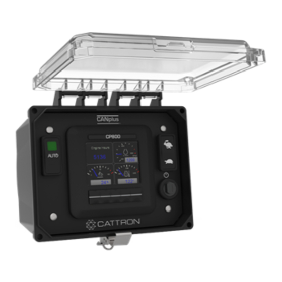
Page 9: Overview
CANplus CP800 Control Panel Operation Manual Overview The CANplus CP800 control panel is a manual and autostart platform for EPA Tier 4 and European Stage V electronically governed diesel engines. Graphical quad-gauge pages or a full-screen dashboard are displayed on the 3.5”... -
Page 10: Display
CANplus CP800 Control Panel Operation Manual Display The CANplus display is a robust, sunlight-viewable 3.5” QVGA color display with five integrated backlit buttons housed in a rugged, water-tight IP66 rated enclosure. The five soft keys simplify and enhance the user interface by providing a configurable auditory beep and positive tactile feedback when pressed. -
Page 11: Analog Gauge
CANplus CP800 Control Panel Operation Manual Analog Gauge Pages Analog Gauge Pages provide four independently configurable pages of analog gauges. To enable Analog Gauge Pages, press any of the first four buttons to show the top level button bar and then press button 1 to cycle through the pages. -
Page 12: Autostart Dashboard
CANplus CP800 Control Panel Operation Manual Note: Some items like Engine Hours are displayed as a digital value. All 16 gauges may be configured to create an application-specific view of the data. With Tech or Admin level Configuration → Display → access, the four analog gauge pages can be configured using the following menu: Gauges →... -
Page 13: Alarm List
Equipment Fault Code Diagnostic Information system (additional information is available at www.cattron.com/resources/cattron-patents). Pressing this button again displays a QR-code specific to this alarm. The QR-code can be scanned using the camera on most smart phones. When scanned, the phone will give an option to automatically jump to the RemoteIQ (RiQ) Fault website. -
Page 14: Menus
CANplus CP800 Control Panel Operation Manual Menus The menu pages can be accessed by pressing and holding button 5. After 1 second, the top-level menu page will appear. From there the functions of the five display buttons change to allow navigation and selecting and modifying parameters. - Page 15 CANplus CP800 Control Panel Operation Manual – Quad Gauge Pages (configure which gauges will be displayed) Power Timeouts • System Restore Defaults (recall factory defaults) • • Update IOB FW • Import Config (import a new configuration file from the USB port) •...
- Page 16 CANplus CP800 Control Panel Operation Manual Autostart Behavior • – Operation High→Low Low→High – Start-Stop With Dual Switch, Single Switch, Transducer, Transducer w/ Backup Switches, Scheduler Only, Timed Run – Maintain Transducer Level Enabled, Disabled Function Low→High · High→Low · Target Point Throttle Aggressiveness Error...
- Page 17 CANplus CP800 Control Panel Operation Manual · Calibration Zero Offset Transducer 1 Low Warning Alarm · Low Shutdown Alarm · · High Warning Alarm · High Shutdown Alarm • Scheduler – Method Disabled Override Allowed Times – Schedule A-P Timed Run •...
-
Page 18: Access Levels
CANplus CP800 Control Panel Operation Manual 3.8.2 Access Levels The available menu items are dependent upon the current access level. The current access level is shown in the upper right corner while in the menus. The CP800 supports up to three independent PINs that are configurable. The standard CANplus configuration has the following PINs settings: •... -
Page 19: Engine Setup
CANplus CP800 Control Panel Operation Manual Engine Setup Setting up the panel for a particular engine can be done through the menus. However, some engines require changes to multiple parameters. For this reason, using the CANplus Customizer is highly recommended for creating configurations for a particular engine as it will automatically create configurations with the necessary parameter changes, as well as populate commonly used gauges for the particular engine. -
Page 20: Canplus Control
For a video showing Setup and Demonstration on a CP1000 (the CP800 functions the similarly), Click or go to https://www.cattron.com/resources/support-videos/canplus-control-throttling-and-control-support-videos/canplus-cp1000-control-dynamic-throttling/ Pause at Run speed Single press and hold to ramp to the configurable run RPM and pause to allow throttling adjustments from that point... -
Page 21: Linear Throttling
Linear Throttling Allows an external device such as PLC to control the throttle using a 4-20 mA input here For a video showing Setup and Demonstration on a CP1000 (the CP800 functions the similarly), Click or go to https://www.cattron.com/resources/support-videos/canplus-control-throttling-and-control-support-videos/canplus-cp1000-control-linear-throttling/ Auto/Manual mode Toggle Auto/Manual Mode Toggle allows switching between these two modes without an engine shutdown here... -
Page 22: Manual Operation
CANplus CP800 Control Panel Operation Manual Manual Operation Use the following steps for manual operation: 1. Ensure that the Auxiliary Engine Stop (if fitted) is not activated. 2. Turn the keyswitch to the run position. 3. Turn the keyswitch clockwise to the start position and hold until the engine successfully starts. 4. -
Page 23: Stopping The Engine
CANplus CP800 Control Panel Operation Manual maximum speed is achieved Pressing and releasing the turtle icon decreases the speed by the switch increment value (default = • 25 RPM) Pressing and holding the turtle icon causes the speed to decrease (ramp) until the minimum speed is •... -
Page 24: Autostart Operation
CANplus CP800 Control Panel Operation Manual Autostart Operation Prerequisites The CP800 is capable of starting and stopping the engine based on external triggers and/or timed schedules. Note: It is important to note that the engine may start without warning or notice. The CP800 is equipped with an Autostart warning alarm. -
Page 25: Behavior
CANplus CP800 Control Panel Operation Manual Behavior 7.4.1 Configuring Operation Configuring Autostart begins with selecting the desired behavior. The two choices are as follows: 1. High to low, examples: • High water level to low water level • High pressure to low pressure •... - Page 26 CANplus CP800 Control Panel Operation Manual The following table describes the Start/Stop events when behavior operation is set to “Low to High” (switches/floats are normally open): Start/Stop Events Engine Starts When Engine Stops When Single Switch SW1 is open SW1 is closed Dual Switch SW1 and SW2 are both open SW1 and SW2 are both closed...
-
Page 27: Configuring The Transducer
CANplus CP800 Control Panel Operation Manual Faults Transducer Level Low-Level Switch High-Level Switch Result Above Low-Level Point Open — Transducer is within normal operating range but value is incorrect (too high) because low-level float should be closed Below High-Level Point —... -
Page 28: Configuring Start And Stop Delays
CANplus CP800 Control Panel Operation Manual depicted in the graph by the green “Correct” throttle aggressiveness line. However, if the gain is set too low, the engine’s RPM may never get to the proper range to maintain the target value as depicted in the graph by the yellow “Too Low”... -
Page 29: Ramp Profile
CANplus CP800 Control Panel Operation Manual 7.4.5 Ramp Profile The Autoramp™ profile allows the use of configurable warm up and cool down profiles to help protect engines and other assets such as plumbing, or to ensure proper ramp up and down of pressure or flow. An example is shown below. -
Page 30: Configuring Rpm And Time Profile Settings
CANplus CP800 Control Panel Operation Manual 7.4.6 Configuring RPM and Time Profile Settings Setting Description Idle RPM Selects the RPM that the control system will request for idle speed. If the engine is started, it will always begin running at Idle speed. Intermediate RPM Selects the RPM that the control system will request for intermediate speed. -
Page 31: Scheduler
CANplus CP800 Control Panel Operation Manual – Display Units Units that are displayed on the gauges – Calibration Zero Offset Offset to calibrate the 4 mA value (plus or minus 5%) • Low Warning Alarm – Value in display units that will generate a Low warning •... -
Page 32: Configuration
The software suite is meticulously maintained and regularly updated. These free updates include software enhancements and new functionality, and they ensure compatibility with evolving technologies. Please see the Resources section at www.cattron.com/CP800. The CANplus Config Kit (Part Number 010-6750-01) includes the following: •... -
Page 33: Customizer Software Suite And A Usb Drive
CANplus CP800 Control Panel Operation Manual CANplus Customizer Software Suite and a USB Drive Click here to view the CP800 Import, Export, Configurations and Software Upgrade video. The CP800 introduces the ability to import and export configurations using a USB drive, avoiding the need to purchase and have onsite a CANplus Config Kit as well as the need to disconnect the panel from the engine. -
Page 34: Firmware Update
CANplus CP800 Control Panel Operation Manual Firmware Update The CP800 introduces the ability to update the application firmware using a USB drive. The panel’s USB port can be accessed by simply removing the four front faceplate screws. The USB port location is protected by a water-tight rubber plug, as shown below. -
Page 35: Troubleshooting
CANplus CP800 Control Panel Operation Manual 9.1.3 Troubleshooting During the update process, if the screen turns at any point after the BLUE screen has been shown, this means that there were problems reading the information on the USB Stick. If this happens, the software update has not been applied. -
Page 36: Miscellaneous
CANplus CP800 Control Panel Operation Manual Miscellaneous 10.1 Emissions System Functionality Note: GENERAL EMISSIONS DISCLAIMER This panel may include provision(s) for operator input such as FORCE REGENERATION, INHIBIT REGENERATION, INTERLOCK and others specific to US and International emissions regulations. Responsibility for emissions-related inputs and compliance with emissions regulations is solely that of the owner and/or operator of the machine/engine on which this panel is connected. -
Page 37: Typical J1939 Wiring Topology
CANplus CP800 Control Panel Operation Manual 10.2.1 Typical J1939 Wiring Topology 10.2.2 Engine Harness Connector Connection to the engine is provided by a Deutsch/TE 21 pin connector (Part Number HDP24-24-21PE). The mating connector is Deutsch/TE (Part Number HDP26-24-21SE). Signals are shown in Table Table 1: Engine Harness Connection Signal Description... -
Page 38: Sealed Connectors
Maximum Starter Relay Excitation Current Draw 5 A @ 12 V 3 A @ 24 V Cattron provides suitable heavy duty relays and generic starter relay wiring kits in both 12 V and 24 V; please contact your LOFA reseller for more information. -
Page 39: Battery Circuit Requirements
Powering the control system through a 30 A fused dedicated circuit reduces the possibility of system damage. CAUTION DISCONNECTING THE BATTERY WHILE THE ENGINE IS RUNNING MAY RESULT IN DAMAGE TO ELECTRICAL COMPONENTS. WHEN USING A BATTERY DISCONNECT SWITCH, CATTRON RECOMMENDS USING A TWO POLE SWITCH TO DISCONNECT BOTH THE BATTERY AND ALTERNATOR OUTPUT. -
Page 40: Welding On Equipment With Electronic Controls
CANplus CP800 Control Panel Operation Manual Inductive devices such as relays, solenoids and motors generate voltage transients and noise in electrical circuits. Unsuppressed voltage transients can exceed SAE specifications and damage electronic controls. Relays and solenoids with built-in voltage transient suppression diodes are recommended whenever possible. Ensure the proper installation of diodes when built-in voltage transient suppression is not available. -
Page 41: Testing A Warning Or Shutdown
CANplus CP800 Control Panel Operation Manual Control system performs normal self-test, engine cranks, runs and shuts down Possible Cause Possible Remedy Engine Stop LED illuminated Correct ECU stop condition, use ECU diagnostics Display does not display data Possible Cause Possible Remedy Display lost power Turn on key, verify display plugged into harness Engine Source address incorrect... -
Page 42: Diagnostic Trouble Codes (Dtc)
CANplus CP800 Control Panel Operation Manual 5. Reinstall the terminator resistor and reconnect the battery. If the ECU diagnostic tool is available, use it to verify that the ECU is transmitting CAN data. Refer to the ECU documentation to identify and correct the error. If another panel is available for testing, replace the panel to determine if the error is in the panel. - Page 43 CANplus CP800 Control Panel Operation Manual Description Abnormal frequency, pulse width or period Abnormal update rate Abnormal rate of change Failure mode not identifiable Bad intelligent device or component Out of calibration Special instructions Data valid but above normal operational range (least severe) Data valid but above normal operational range (moderately severe) Data valid but below normal operational range (least severe) Data valid but below normal operational range (moderately severe)
-
Page 44: Technical Support
CANplus CP800 Control Panel Operation Manual Technical Support For remote and communication control systems support, parts and repair, or technical support, visit us online at: www.cattron.com/contact. 9M02-1000-A201-EN Revision E... - Page 45 Due to continuous product improvement, the information provided in this document is subject to change without notice. Cattron Support For remote and communication control systems support, parts and repair, or technical support, visit us online at: www.cattron.com/contact Cattron North America Inc., 655 N River Rd NW, Suite A, Warren, OH 44483 9M02-1000-A201-EN Revision D...
Need help?
Do you have a question about the CANplus CP800 and is the answer not in the manual?
Questions and answers