Cattron CANplus CP750-E Operation Manual
Hide thumbs
Also See for CANplus CP750-E:
- Installation manual (16 pages) ,
- Operation manual (72 pages)
Table of Contents
Advertisement
Quick Links
Advertisement
Table of Contents

Related Manuals for Cattron CANplus CP750-E


Summary of Contents for Cattron CANplus CP750-E
- Page 1 CANplus ™ CP750-E Control Panel Operation Manual 9M02-1000-A501-EN...
- Page 2 Cattron makes no warranties as to non-infringement nor as to the fitness, merchantability, or sustainability of any Cattron products for any specific or general uses. Cattron Holdings, Inc., or any of its affiliates or agents shall not be liable for incidental or consequential damages of any kind.
-
Page 3: Table Of Contents
CANplus CP750-E Control Panel Operation Manual Important Safety and Emissions Information _______________________________ 6 Safety Notation ___________________________________________________________ 6 Safety Instructions ________________________________________________________ 6 Auxiliary Engine Stop Disclaimer ____________________________________________ 7 General Emissions Disclaimer ______________________________________________ 8 Exhaust Emissions Compliance Disclaimer ___________________________________ 8 Overview _____________________________________________________________ 8... - Page 4 CANplus CP750-E Control Panel Operation Manual 6.4.4 Configuring Start and Stop Delays ________________________________________________ 28 6.4.5 Ramp Profile _________________________________________________________________ 28 6.4.6 Configuring RPM and Time Profile Settings _________________________________________ 29 Transducers ____________________________________________________________ 29 6.5.1 Autostart Triggers _____________________________________________________________ 29 6.5.2 Setup _______________________________________________________________________ 29...
- Page 5 CANplus CP750-E Control Panel Operation Manual 11.2.2 Engine Harness Connector ____________________________________________________ 36 11.2.3 Sealed Connectors __________________________________________________________ 37 11.2.4 Unsealed Connectors ________________________________________________________ 37 11.2.5 Harness Routing ____________________________________________________________ 37 11.3 Engine Starter Excitation Connection _______________________________________ 37 11.3.1 Starter Relay _______________________________________________________________ 37 11.3.2 Battery Circuit Requirements __________________________________________________ 38 11.3.3...
-
Page 6: Important Safety And Emissions Information
CANplus CP750-E Control Panel Operation Manual Important Safety and Emissions Information Safety Notation This manual uses the following conventions to present IMPORTANT SAFETY INFORMATION to you. Please read and follow ALL SAFETY INSTRUCTIONS. WARNING IMPORTANT AND URGENT SAFETY INFORMATION – A HAZARD THAT WILL, IF NOT AVOIDED, CAUSE SERIOUS INJURY OR LOSS OF LIFE. -
Page 7: Auxiliary Engine Stop Disclaimer
CANplus CP750-E Control Panel Operation Manual CAUTION CANPLUS PRODUCTS ARE NOT DESIGNED FOR, OR INTENDED FOR USE ON, APPLICATIONS REQUIRING EXPLOSIVE PROOF COMPONENTS. FURTHER, CANPLUS PRODUCTS ARE NOT DESIGNED FOR, OR INTENDED FOR APPLICATION WITHIN, HAZARDOUS OR EXPLOSIVE ENVIRONMENTS. CAUTION... -
Page 8: General Emissions Disclaimer
ECU initiated emissions event. Overview The CANplus CP750-E control panel is a manual and autostart platform for EPA Tier 3, EPA Tier 4 (interim), EPA Tier 4 and EU Stage V electronically governed diesel or natural gas engines. It can also control mechanically governed diesel engines. -
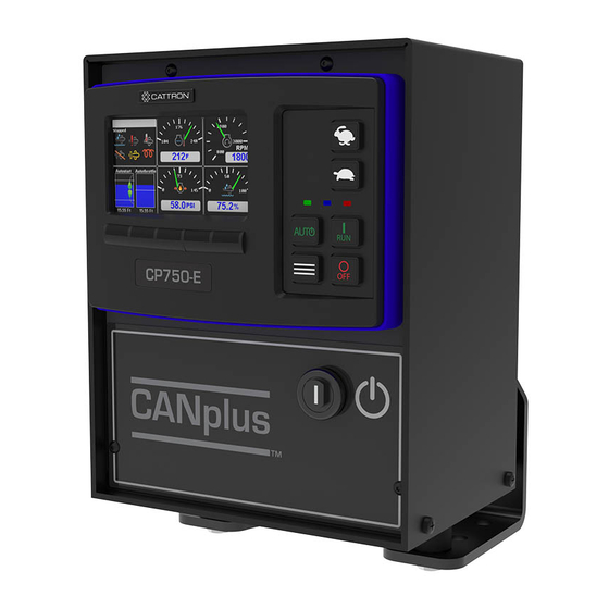
Page 9: Display
CANplus CP750-E Control Panel Operation Manual Display The CANplus display is a robust, sunlight-viewable 4.3” WQVGA color display with five integrated backlit display buttons and eight large control buttons housed in a rugged, water-tight IP66 rated enclosure. The five display keys simplify and enhance the user interface by providing positive tactile feedback when pressed. -
Page 10: Gauge Pages
CANplus CP750-E Control Panel Operation Manual Gauge Pages There are four independently configurable pages of analogy gauges. To enable Analog Gauge Pages, press any of the first four buttons to show the top-level button bar and then press button 1 to cycle through the pages. The current page is indicated by the number in the center of the screen, as shown below. -
Page 11: Active Alarms
Equipment Fault Code Diagnostic Information system (additional information is available at www.cattron.com/resources/cattron-patents). Pressing this button again displays a QR-code specific to this alarm. The QR-code can be scanned using the camera on most smart phones. When scanned, the phone will give an option to automatically jump to the RemoteIQ™... -
Page 12: Service Timers
CANplus CP750-E Control Panel Operation Manual Service Timers The panel’s display provides 16 service timers to alert the operator of required maintenance. The time interval for each timer can be adjusted in increments of 10 hours. A popup message is displayed after completion of the display’s self-test if a timer (or timers) has expired, alerting the user that service is required. -
Page 13: Menus
CANplus CP750-E Control Panel Operation Manual Menus The menu pages can be accessed by pressing button 5. The top-level menu page will then appear. From there the functions of the five display buttons change to allow navigation and selecting and modifying parameters. - Page 14 CANplus CP750-E Control Panel Operation Manual • Gauges – Quadrant Page 1-4 Top Left Top Right Bottom Left Bottom Right • Power Timeout System Setup Configurations & Updates • – Restore Defaults – Import Configuration – Export Configuration – Saved Configurations –...
- Page 15 CANplus CP750-E Control Panel Operation Manual – Engine Data Sources Tachometer Engine Hours Coolant Temp Oil Pressure – FTP F34 Oil Life Reset Engine Shutdown • About Logging • – Start CAN Trace – Stop CAN Trace – Cranking Voltage Log –...
- Page 16 CANplus CP750-E Control Panel Operation Manual Low → High – Start-Stop With Dual Switch, Single Switch, Transducer, Transducer w/ Backup Switches, Scheduler Only, Timed Run, Cycle Run, Single Start/Stop, Remote Control, Pressure Washer – Start Enable Delay (s) – Stop Enable Delay (s) –...
- Page 17 CANplus CP750-E Control Panel Operation Manual · Low Shutdown Alarm High Warning Alarm · High Shutdown Alarm · Type & Range · Scheduler • – Method Allowed Times, Disabled, Override – Schedule A-P Days of the Week Start Time hh:mm Stop Time hh:mm •...
- Page 18 CANplus CP750-E Control Panel Operation Manual Active When Running Ignore Delay (s) Enable Delay (s) Disable Delay (s) Inputs • – Event Manager Oil Pressure Coolant Temp Fuel Level Battery Voltage Engine Speed – Aux Switch 1-6 Armed When ·...
-
Page 19: Access Levels
CANplus CP750-E Control Panel Operation Manual 3.7.2 Access Levels The available menu items are dependent upon the current access level. The current access level is shown in the upper right corner while in the menus. The CP750-E supports up to three independent PINs that are configurable. -
Page 20: Quick Access Menu
CANplus CP750-E Control Panel Operation Manual 3.7.3 Quick Access Menu The Quick Access Menu can be opened by pressing the menu control button . This menu contains commonly accessed menu items. All access levels open this menu, and it is not affected by the Menu PIN Required setting. -
Page 21: Manual Operation
CANplus CP750-E Control Panel Operation Manual 1. Calibrate the tachometer by selecting Calibrate Tach. a) With the engine at idle, measure the RPM using a photo-tachometer or handheld tachometer. Better RPM accuracy is achieved if the engine is allowed to warm up. -
Page 22: Rotary Throttle Control
CANplus CP750-E Control Panel Operation Manual Note: Throttle control requires CAN throttling to be enabled in the ECU. CAN throttling is also known as Torque Speed Control or TSC1. When first started, the requested engine speed is Idle RPM. Pressing and releasing the rabbit icon increases the speed by the switch/rotary increment value •... -
Page 23: Autostart Operation
CANplus CP750-E Control Panel Operation Manual Autostart Operation Prerequisites The CP750-E can start and stop the engine based on external triggers and/or timed schedules. Note: It is important to note that the engine may start without warning or notice. The CP750-E is equipped with an Autostart warning alarm. -
Page 24: Configuring Operation
CANplus CP750-E Control Panel Operation Manual 6.4.1 Configuring Operation Configuring Autostart begins with selecting the desired behavior. The two choices are as follows: 1. High to low, examples: • High water level to low water level • High pressure to low pressure •... - Page 25 CANplus CP750-E Control Panel Operation Manual The following table describes the Start/Stop events when behavior operation is set to “High to Low” (switches/floats are normally open): Start/Stop Events Engine Starts When Engine Stops When Single Switch SW1 is closed SW1 is open...
-
Page 26: Configuring The Transducer
CANplus CP750-E Control Panel Operation Manual Faults Transducer Level Low-Level Switch High-Level Switch Result Above Low-Level Point Open — Transducer is within normal operating range, but value is incorrect (too high) because low- level float should be closed Below High-Level Point —... - Page 27 CANplus CP750-E Control Panel Operation Manual car going uphill will speed up slowly and therefore needs more aggressive throttling. To adjust how quickly the Autostart → Behavior → control panel ramps the throttle up or down for a particular application, go to the Maintain Transducer Level →...
-
Page 28: Configuring Start And Stop Delays
CANplus CP750-E Control Panel Operation Manual 6.4.4 Configuring Start and Stop Delays In situations where start or stop conditions may be met briefly, yet repeated start/stop cycles of the engine need be avoided, two settings allow a delay to be added before a specific input condition is recognized. An example of such use is where a float switch is installed in choppy water. -
Page 29: Configuring Rpm And Time Profile Settings
CANplus CP750-E Control Panel Operation Manual 6.4.6 Configuring RPM and Time Profile Settings Setting Description Idle RPM Selects the RPM that the control system will request for idle speed. If the engine is started, it will always begin running at Idle speed. -
Page 30: Scheduler
CANplus CP750-E Control Panel Operation Manual – 4 mA Scaled Value Value in setup units represented by a 4-mA reading – 20 mA Scaled Value Value in setup units represented by a 20-mA reading – Setup Units Units used to setup the 4 mA and 20 mA scaled values –... -
Page 31: Canplus Control
CANplus CP750-E Control Panel Operation Manual CANplus Control The CP750-E has expanded throttle and control capabilities, which provides users with more options to control mechanically or electronically governed engines. CANplus Control Throttling Options: • Controlled Off • Auto/Manual mode Toggle Momentary Rabbit/Turtle Keys •... -
Page 32: Auto/Manual Mode Toggle
CANplus CP750-E Control Panel Operation Manual Click for a video showing Setup and Demonstration or go to here https://youtu.be/3HILfk1TSV8 Auto/Manual mode Toggle Auto/Manual Mode Toggle allows switching between modes without an engine shutdown Momentary Rabbit/Turtle Keys Momentary Rabbit/Turtle Keys Throttle adjustment via momentary rocker switch... -
Page 33: Configuration
The software suite is meticulously maintained and regularly updated. These free updates include software enhancements and new functionality, and they ensure compatibility with evolving technologies. Please see the Resources section at www.cattron.com/CP750-E. The CANplus Config Kit (Part Number 010-6750-01) includes the following: •... -
Page 34: Firmware And License File Update
CANplus CP750-E Control Panel Operation Manual when importing a new configuration. When finished with exporting or importing configurations, remove the USB drive and reinstall the dirt and dust rubber plug. Firmware and License file Update The CP750-E introduces the ability to update the application firmware using a USB drive. -
Page 35: Miscellaneous
CANplus CP750-E Control Panel Operation Manual Miscellaneous 11.1 Emissions System Functionality Note: GENERAL EMISSIONS DISCLAIMER This panel may include provision(s) for operator input such as FORCE REGENERATION, INHIBIT REGENERATION, INTERLOCK, and others specific to US and International emissions regulations. Responsibility for emissions-related inputs and compliance with emissions regulations is solely that of the owner and/or operator of the machine/engine on which this panel is connected. -
Page 36: Typical J1939 Wiring Topology
CANplus CP750-E Control Panel Operation Manual 11.2.1 Typical J1939 Wiring Topology 11.2.2 Engine Harness Connector Connection to the engine is provided by a Deutsch/TE 21 pin connector (Part Number HDP24-24-21PE). The mating connector is Deutsch/TE (Part Number HDP26-24-21SE). Signals are shown in Table 1. -
Page 37: Sealed Connectors
Maximum Starter Relay Excitation Current Draw 5 A @ 12 V 3 A @ 24 V Cattron provides suitable heavy-duty relays and generic starter relay wiring kits in both 12 V and 24 V; please contact your LOFA reseller for more information. -
Page 38: Battery Circuit Requirements
MUST BE FREE FROM FOREIGN MATERIALS, INCLUDING PAINT, WHICH MAY INTERFERE WITH PROPER CONNECTION. A RELIABLE 30 A MAXIMUM FUSED POWER CIRCUIT MUST BE PROVIDED FOR THE CONTROL SYSTEM. CATTRON RECOMMENDS THE POWER CONNECTION BE MADE DIRECTLY TO THE BATTERY WITH THE FUSE ELECTRICALLY CLOSE TO THE BATTERY. -
Page 39: Welding On Equipment With Electronic Controls
CANplus CP750-E Control Panel Operation Manual THE INSTALLATION OF VOLTAGE TRANSIENT SUPPRESSION AT THE TRANSIENT SOURCE IS REQUIRED. CATTRON FOLLOWS SAE RECOMMENDED ELECTRICAL ENVIRONMENT PRACTICES. Inductive devices such as relays, solenoids and motors generate voltage transients and noise in electrical circuits. -
Page 40: Testing A Warning Or Shutdown
CANplus CP750-E Control Panel Operation Manual Possible Cause Possible Remedy Faulty control system Repair or replace control system Control system performs normal self-test, engine cranks, runs and shuts down Possible Cause Possible Remedy Engine Stop LED illuminated Correct ECU stop condition, use ECU diagnostics... -
Page 41: Diagnostic Trouble Codes (Dtc)
CANplus CP750-E Control Panel Operation Manual An ohmmeter reading of around 120 Ω indicates the bus to the terminator in the panel is complete and the problem is between the panel and the engine terminator. An open circuit ohmmeter reading indicates the bus to the engine terminator is complete and the problem is between the panel and the diagnostic plug. - Page 42 CANplus CP750-E Control Panel Operation Manual Description Current below normal or open circuit Current above normal or grounded circuit Mechanical system not responding properly Abnormal frequency, pulse width or period Abnormal update rate Abnormal rate of change Failure mode not identifiable...
-
Page 43: Certifications
CANplus CP750-E Control Panel Operation Manual Certifications 12.1 FCC Part 15 Certification This device complies with Part 15 of the FCC Rules. Operation is subject to the following two conditions: (1) this device may not cause harmful interference, and (2) this device must accept any interference received, including interference that may cause undesired operation. -
Page 44: Industry Canada Certification
CANplus CP750-E Control Panel Operation Manual 12.2 Industry Canada Certification Note: These statements are required to be listed in both English and French Languages. This device complies with Industry Canada license-exempt RSS standard(s). Operation is subject to the following two conditions: (1) this device may not cause interference, and (2) this device must accept any interference, including interference that may cause undesired operation of the device. -
Page 45: Technical Support
CANplus CP750-E Control Panel Operation Manual Technical Support For remote and communication control systems support, parts and repair, or technical support, visit us online at: www.cattron.com/contact. Icons Glossary 14.1 Gauge Icons Icon Description Fuel Pressure Fuel Level Engine Oil Level... - Page 46 CANplus CP750-E Control Panel Operation Manual Icon Description Transmission Oil Pressure Battery Voltage Inlet Air Temperature Exhaust Gas Temperature Fuel Temperature Engine Oil Temperature Transmission Oil Temperature Fuel Consumption Rate Engine Speed Total Engine Hours 1761 SCR Fluid Level 3719...
-
Page 47: Status Gauge Icons
CANplus CP750-E Control Panel Operation Manual Icon Description 3720 Ash Percentage 14.2 Status Gauge Icons NOTE: Not all engine templates use the icons on this page. Icon requirements are defined by the engine manufacture. Icon Description Preheat Active / Wait to Start... -
Page 48: Status Bar Icons
CANplus CP750-E Control Panel Operation Manual Icon Description Aftertreatment Fault - Most Serve Engine Derate Active Stop Engine Check Engine 14.3 Status Bar Icons Icon Description Autostart Active 14.4 Autostart Dashboard Icons Icon Description AutoStart - AutoStart Switch Active AutoStart - AutoStart Switch Inactive... -
Page 49: Menu Icons
CANplus CP750-E Control Panel Operation Manual Icon Description AutoStart - Stop Event Requirements 14.5 Menu Icons Icon Description Action - Acknowledge Alarms Action - Enter Submenu Action - Exit Current Menu Action - Navigate Down Action - Navigate Up Action - Request Stored Alarms... - Page 50 CANplus CP750-E Control Panel Operation Manual Icon Description Navigation - Select Gauge Page / Rotate Gauge Pages Navigation - Settings Menu *Patent Pending 9M02-1000-A501-EN Revision B...
- Page 51 Control Panel Operation Manual Due to continuous product improvement, the information provided in this document is subject to change without notice. Cattron SupportFor remote and communication control systems support, parts and repair, or technical support, visit us online at: www.cattron.com/contact Cattron North America Inc., 655 N River Rd NW, Suite A, Warren, OH 44483...
Need help?
Do you have a question about the CANplus CP750-E and is the answer not in the manual?
Questions and answers