Cattron CANplus CP1000 Operation Manual
Hide thumbs
Also See for CANplus CP1000:
- Installation manual (15 pages) ,
- Operation manual (57 pages) ,
- Operation manual (72 pages)
Table of Contents
Advertisement
Quick Links
Advertisement
Table of Contents

Related Manuals for Cattron CANplus CP1000


Summary of Contents for Cattron CANplus CP1000
- Page 1 CANplus CP1000 Control Panel Operation Manual 9M02-1000-A059-EN...
- Page 2 Cattron Holdings, Inc., or any of its affiliates or agents shall not be liable for incidental or consequential damages of any kind. All Cattron products are sold pursuant to the Terms and Conditions of Sale, a copy of which will be furnished upon request. When used as a tradename herein, Cattron means Cattron Holdings, Inc.
-
Page 3: Table Of Contents
CANplus CP1000 Control Panel Operation Manual Contents Important Safety and Emissions Information ...................... 6 Safety Notation ............................6 Safety Instructions............................ 6 Auxiliary Engine Stop Disclaimer ......................7 General Emissions Disclaimer ......................... 8 Exhaust Emissions Compliance Disclaimer ..................... 8 Overview ................................9 Display ................................ - Page 4 CANplus CP1000 Control Panel Operation Manual Autostart Menu ............................25 Behavior ..............................25 6.4.1 Configuring Operation ....................... 26 6.4.2 Configuring Start and Stop Events.................... 26 6.4.3 Configuring the Transducer ...................... 28 6.4.4 Configuring Start and Stop Delays.................... 30 6.4.5 Ramp Profile ..........................30 6.4.6 Configuring RPM and Time Profile Settings ................
- Page 5 CANplus CP1000 Control Panel Operation Manual 9.3.4 Voltage Drop ..........................38 9.3.5 Suppression of Voltage Transients (Spikes) ................38 9.3.6 Welding on Equipment with Electronic Controls ............... 39 Control System Troubleshooting ......................39 9.4.1 Testing a Warning or Shutdown ....................40 9.4.2 Testing CAN ..........................
-
Page 6: Important Safety And Emissions Information
CANplus CP1000 Control Panel Operation Manual Important Safety and Emissions Information 1.1 Safety Notation This manual uses the following conventions to present IMPORTANT SAFETY INFORMATION to you. Please read and follow ALL SAFETY INSTRUCTIONS. WARNING IMPORTANT AND URGENT SAFETY INFORMATION – A HAZARD THAT WILL, IF NOT AVOIDED, CAUSE SERIOUS INJURY OR LOSS OF LIFE. -
Page 7: Auxiliary Engine Stop Disclaimer
CANplus CP1000 Control Panel Operation Manual CAUTION CANPLUS PRODUCTS ARE NOT DESIGNED FOR, OR INTENDED FOR USE ON, APPLICATIONS REQUIRING EXPLOSIVE PROOF COMPONENTS. FURTHER, CANPLUS PRODUCTS ARE NOT DESIGNED FOR, OR INTENDED FOR APPLICATION WITHIN, HAZARDOUS OR EXPLOSIVE ENVIRONMENTS. CAUTION THE INSTALLER OF THIS CANPLUS PRODUCT IS SOLELY RESPONSIBLE FOR ENSURING THAT ALL OSHA, ANSI, CE OR OTHER APPLICABLE STANDARDS ARE MET WITH RESPECT TO... -
Page 8: General Emissions Disclaimer
CANplus CP1000 Control Panel Operation Manual 1.4 General Emissions Disclaimer This panel may include provision(s) for operator input such as FORCE REGENERATION, INHIBIT REGENERATION, INTERLOCK and others specific to US and International emissions regulations. Responsibility for emissions-related inputs and compliance with emissions regulations is solely that of the owner and/or operator of the machine/engine on which this panel is connected. -
Page 9: Overview
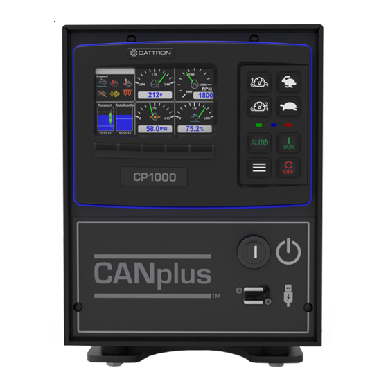
CANplus CP1000 Control Panel Operation Manual Overview The CANplus CP1000 control panel is a manual and autostart platform for EPA Tier 3, EPA Tier 4 (interim), EPA Tier 4 and EU Stage V electronically governed diesel or natural gas engines. It can also control mechanically governed diesel engines. -
Page 10: Display
CANplus CP1000 Control Panel Operation Manual Display display is a robust, sunlight-viewable 4.3” WQVGA color display with five integrated backlit The CANplus display buttons and eight large control buttons housed in a rugged, water-tight IP66 rated enclosure. The five display keys simplify and enhance the user interface by providing positive tactile feedback when pressed. The display can show virtually any SAE J1939 parameter reported by the ECU, including RPM, engine temperature, oil pressure and diagnostic codes. -
Page 11: Gauge
CANplus CP1000 Control Panel Operation Manual Gauge Pages There are four independently configurable pages of analog gauges. To enable Analog Gauge Pages, press any of the first four buttons to show the top level button bar and then press button 1 to cycle through the pages. The current page is indicated by the number in the center of the screen, as shown below. -
Page 12: Autostart And Throttling Dashboards
CANplus CP1000 Control Panel Operation Manual The Autostart gauge shows the start and stop events or levels on the left and the maintain/cruise control level on the right. Autostart and Throttling Dashboards 3.4.1 Autostart Click here to view the autostart dashboard video. When the Dashboard-1 button is pressed, the display will change to the full screen Autostart dashboard, as shown below. -
Page 13: Active Alarms
CANplus CP1000 Control Panel Operation Manual Pressing the Dashboard-2 button again will cause the display to revert back to the gauge page. Active Alarms When an active alarm is received, a flashing popup window is overlaid on the current screen. The popup includes a plain language description in addition to the standard SPN/FMI (Suspect Parameter Number/Failure Mode Indicator) pair defined by the SAE J1939 standard. -
Page 14: Service Timers
Equipment Fault Code Diagnostic Information system (additional information is available at www.cattron.com/resources/cattron-patents). Pressing this button again displays a QR-code specific to this alarm. The QR-code can be scanned using the camera on most smart phones. When scanned, the phone will give an option to automatically jump to the RemoteIQ (RiQ) Fault website. -
Page 15: Menus
CANplus CP1000 Control Panel Operation Manual Menus The menu pages can be accessed by pressing button 5. The top-level menu page will then appear. From there the functions of the five display buttons change to allow navigation and selecting and modifying parameters. Button 1 Button 3 Button 2... - Page 16 CANplus CP1000 Control Panel Operation Manual – Quadrant Page 1-4 Top Left Top Right Bottom Left Bottom Right • Power Timeout System Setup • Restore Defaults • Set Date & Time • Import Configuration • Export Configuration • Load Firmware •...
- Page 17 CANplus CP1000 Control Panel Operation Manual – Yanmar – CAT / Perkins – [Future Engines] • About Telemetry Emission Control • Request Force Regen • Inhibit Regen Disable/Enable Throttle • Minimum RPM • Idle RPM • Maximum RPM • Switch/Rotary –...
- Page 18 CANplus CP1000 Control Panel Operation Manual · Transducer 1,2,3,4,5,6 Target Point Throttle Aggressiveness Error Operation · Controlled Stop, Immediate Stop, Go to Run, Derate • Ramp Profile – RPM Settings Intermediate RPM Run RPM – Time Profile Warm Up Time (s) Ramp Up (s) Intelligent Intermediate Intermediate (s)
- Page 19 CANplus CP1000 Control Panel Operation Manual • Cycle Time – Default State Stopped, Running – Run Time hh:mm – Stop Time hh:mm • Auto Battery Recharge – Auto Battery Enabled Off/On – Recharge Run Speed – Enable Delay (m) – Recharge Time (m) –...
-
Page 20: Access Levels
CANplus CP1000 Control Panel Operation Manual · Always, Stopped, Running Switch Type Engine Stop · Controlled Stop, Immediate Stop, Go to Run, Derate Running Ignore Delay (s) Enable Delay (s) Disable Delay (s) LED Select · Red, Amber LED Flash Rate ·... -
Page 21: Quick Access Menu
CANplus CP1000 Control Panel Operation Manual The panel will prompt for a PIN input. User, Tech or Admin level access will be granted based on which PIN is entered. For example, if the Tech level PIN is entered, Tech level access will be granted, and similarly if Admin or User level PINs are entered. -
Page 22: Engine Setup
CANplus CP1000 Control Panel Operation Manual Engine Setup Setting up the panel for a particular engine can be done through the menus. However, some engines require changes to multiple parameters. For this reason, using the CANplus Customizer is highly recommended for creating configurations for a particular engine as it will automatically create configurations with the necessary parameter changes, as well as populate commonly used gauges for the particular engine. -
Page 23: Manual Operation
CANplus CP1000 Control Panel Operation Manual Manual Operation Use the following steps for manual operation: 1. Ensure that the Auxiliary Engine Stop (if fitted) is not activated. 2. Turn the keyswitch to the run position. 3. Press and hold the Run button. 4. -
Page 24: Rotary Throttle Control
CANplus CP1000 Control Panel Operation Manual Rotary Throttle Control The optional Digital Rotary Throttle uses a rotary switch to simulate the operation of a throttle. When the engine is first started, the requested engine speed is always Idle RPM. Turning the throttle knob clockwise increases the requested engine speed by the switch/rotary increment value (default = 50 RPM). -
Page 25: Autostart Operation
CANplus CP1000 Control Panel Operation Manual Autostart Operation Prerequisites The CP1000 is capable of starting and stopping the engine based on external triggers and/or timed schedules. Note: It is important to note that the engine may start without warning or notice. The CP1000 is equipped with an Autostart warning alarm. -
Page 26: Configuring Operation
CANplus CP1000 Control Panel Operation Manual 6.4.1 Configuring Operation Configuring Autostart begins with selecting the desired behavior. The two choices are as follows: 1. High to low, examples: • High water level to low water level • High pressure to low pressure •... - Page 27 CANplus CP1000 Control Panel Operation Manual The following table describes the Start/Stop events when behavior operation is set to “High to Low” (switches/floats are normally open): Start/Stop Events Engine Starts When Engine Stops When Single Switch SW1 is closed SW1 is open Dual Switch SW1 and SW2 are both closed SW1 and SW2 are both open...
-
Page 28: Configuring The Transducer
CANplus CP1000 Control Panel Operation Manual Faults Transducer Level Low-Level Switch High-Level Switch Result — Above Low-Level Point Open Transducer is within normal operating range but value is incorrect (too high) because low-level float should be closed — Below High-Level Point Closed Transducer is within normal operating range but value is incorrect... - Page 29 CANplus CP1000 Control Panel Operation Manual Autostart → Behavior → control panel ramps the throttle up or down for a particular application, go to the Maintain Transducer Level → Throttle Aggressiveness menu. The higher the number, the more aggressive or quicker the control panel ramps the throttle up or down to maintain the level.
-
Page 30: Configuring Start And Stop Delays
CANplus CP1000 Control Panel Operation Manual 6.4.4 Configuring Start and Stop Delays In situations where start or stop conditions may be met briefly, yet repeated start/stop cycles of the engine need be avoided, two settings allow a delay to be added before a specific input condition is recognized. An example of such use is where a float switch is installed in choppy water. -
Page 31: Configuring Rpm And Time Profile Settings
CANplus CP1000 Control Panel Operation Manual 6.4.6 Configuring RPM and Time Profile Settings Setting Description Idle RPM Selects the RPM that the control system will request for idle speed. If the engine is started, it will always begin running at Idle speed. Intermediate RPM Selects the RPM that the control system will request for intermediate speed. -
Page 32: Scheduler
CANplus CP1000 Control Panel Operation Manual • Type and Range – 4 mA Scaled Value Value in setup units represented by a 4 mA reading – 20 mA Scaled Value Value in setup units represented by a 20 mA reading –... -
Page 33: Configuration
The software suite is meticulously maintained and regularly updated. These free updates include software enhancements and new functionality, and they ensure compatibility with evolving technologies. Please see the Resources section at www.cattron.com/cp1000. The CANplus Config Kit (Part Number 010-6750-01) includes the following: •... -
Page 34: Firmware Update
CANplus CP1000 Control Panel Operation Manual Firmware Update The CP1000 introduces the ability to update the application firmware using a USB drive. Updating via USB Drive 8.1.1 Preparation Copy the update file into the root directory of an empty USB stick, which has been formatted with FAT32. 8.1.2 Procedure System →... -
Page 35: Miscellaneous
CANplus CP1000 Control Panel Operation Manual Miscellaneous Emissions System Functionality Note: GENERAL EMISSIONS DISCLAIMER This panel may include provision(s) for operator input such as FORCE REGENERATION, INHIBIT REGENERATION, INTERLOCK, and others specific to US and International emissions regulations. Responsibility for emissions-related inputs and compliance with emissions regulations is solely that of the owner and/or operator of the machine/engine on which this panel is connected. -
Page 36: Typical J1939 Wiring Topology
CANplus CP1000 Control Panel Operation Manual 9.2.1 Typical J1939 Wiring Topology 9.2.2 Engine Harness Connector Connection to the engine is provided by a Deutsch/TE 21 pin connector (Part Number HDP24-24-21PE). The mating connector is Deutsch/TE (Part Number HDP26-24-21SE). Signals are shown in Table Table 1: Engine Harness Connection Signal Description... -
Page 37: Sealed Connectors
Maximum Starter Relay Excitation Current Draw 5 A @ 12 V 3 A @ 24 V Cattron provides suitable heavy duty relays and generic starter relay wiring kits in both 12 V and 24 V; please contact your LOFA reseller for more information. -
Page 38: Battery Circuit Requirements
MUST BE FREE FROM FOREIGN MATERIALS, INCLUDING PAINT, WHICH MAY INTERFERE WITH PROPER CONNECTION. A RELIABLE 30 A MAXIMUM FUSED POWER CIRCUIT MUST BE PROVIDED FOR THE CONTROL SYSTEM. CATTRON RECOMMENDS THE POWER CONNECTION BE MADE DIRECTLY TO THE BATTERY WITH THE FUSE ELECTRICALLY CLOSE TO THE BATTERY. -
Page 39: Welding On Equipment With Electronic Controls
CANplus CP1000 Control Panel Operation Manual Inductive devices such as relays, solenoids and motors generate voltage transients and noise in electrical circuits. Unsuppressed voltage transients can exceed SAE specifications and damage electronic controls. Relays and solenoids with built-in voltage transient suppression diodes are recommended whenever possible. Ensure the proper installation of diodes when built-in voltage transient suppression is not available. -
Page 40: Testing A Warning Or Shutdown
CANplus CP1000 Control Panel Operation Manual Control system performs normal self-test, engine cranks, runs and shuts down Possible Cause Possible Remedy Engine Stop LED illuminated Correct ECU stop condition, use ECU diagnostics Display does not display data Possible Cause Possible Remedy Display lost power Turn on key, verify display plugged into harness Engine Source address incorrect... -
Page 41: Diagnostic Trouble Codes (Dtc)
CANplus CP1000 Control Panel Operation Manual 5. Reinstall the terminator resistor and reconnect the battery. If the ECU diagnostic tool is available, use it to verify that the ECU is transmitting CAN data. Refer to the ECU documentation to identify and correct the error. If another panel is available for testing, replace the panel to determine if the error is in the panel. - Page 42 CANplus CP1000 Control Panel Operation Manual Description Abnormal frequency, pulse width or period Abnormal update rate Abnormal rate of change Failure mode not identifiable Bad intelligent device or component Out of calibration Special instructions Data valid but above normal operational range (least severe) Data valid but above normal operational range (moderately severe) Data valid but below normal operational range (least severe) Data valid but below normal operational range (moderately severe)
-
Page 43: Certifications
CANplus CP1000 Control Panel Operation Manual Certifications 10.1 FCC Part 15 Certification This device complies with Part 15 of the FCC Rules. Operation is subject to the following two conditions: (1) this device may not cause harmful interference, and (2) this device must accept any interference received, including interference that may cause undesired operation. -
Page 44: Industry Canada Certification
CANplus CP1000 Control Panel Operation Manual 10.2 Industry Canada Certification Note: These statements are required to be listed in both English and French Languages. This device complies with Industry Canada licence-exempt RSS standard(s). Operation is subject to the following two conditions: (1) this device may not cause interference, and (2) this device must accept any interference, including interference that may cause undesired operation of the device. -
Page 45: Technical Support
CANplus CP1000 Control Panel Operation Manual Technical Support For remote and communication control systems support, parts and repair, or technical support, visit us online at: www.cattron.com/contact. 9M02-1000-A059-EN Revision 2.0... - Page 46 Due to continuous product improvement, the information provided in this document is subject to change without notice. Cattron Support For remote and communication control systems support, parts and repair, or technical support, visit us online at: www.cattron.com/contact Cattron North America Inc., 655 N River Rd NW, Suite A, Warren, OH 44483 9M02-1000-A059-EN Revision 2.0...
Need help?
Do you have a question about the CANplus CP1000 and is the answer not in the manual?
Questions and answers