Table of Contents
Advertisement
Quick Links
Advertisement
Table of Contents

Related Manuals for Advantech IE-Giga-MiniMc


Summary of Contents for Advantech IE-Giga-MiniMc
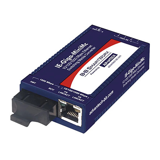
- Page 1 User Manual IE-Giga-MiniMc Industrial Miniature Media Converter...
- Page 2 No part of this manual may be reproduced, copied, translated or transmitted in any form or by any means without the prior written permission of Advantech Co., Ltd. Information provided in this manual is intended to be accurate and reliable.
- Page 3 Technical Support and Assistance Visit the Advantech web site at www.advantech.com/support where you can find the latest information about the product. Contact your distributor, sales representative, or Advantech's customer service center for technical support if you need additional assistance.
- Page 4 Before setting up the system, check that the items listed below are included and in good condition. If any item does not accord with the table, please contact your dealer immediately. 1 x IE-Giga-MiniMc device 1 x Universal power adapter with US/EU/UK/AU/JP plugs (optional) ...
- Page 5 The equipment has obvious signs of breakage. DO NOT LEAVE THIS EQUIPMENT IN AN ENVIRONMENT WHERE THE STORAGE TEMPERATURE MAY GO -40°C (-40°F) ~ 85°C (185°F). THIS COULD DAMAGE THE EQUIPMENT. THE EQUIPMENT SHOULD BE IN A CONTROLLED ENVIRONMENT. IE-Giga-MiniMc User Manual...
- Page 6 – Wenn das Gerät nicht der Bedienungsanleitung entsprechend funktioniert oder Sie mit Hilfe dieser Anleitung keine Verbesserung erzielen. – Das Gerät ist gefallen und/oder das Gehäuse ist beschädigt. – Wenn das Gerät deutliche Anzeichen eines Defektes aufweist. IE-Giga-MiniMc User Manual...
- Page 7 Always disconnect the power from the device before servicing it. Before plugging a cable into any port, discharge the voltage stored on the cable by touching the electrical contacts to the ground surface. IE-Giga-MiniMc User Manual...
-
Page 8: Table Of Contents
Front View..................5 1.5.2 Rear View ..................5 1.5.3 System LED Panel................ 5 Installing the IE-GIGA-MINIMC..............6 Hardware Mounting................... 6 Powering the IE-GIGA-MINIMC ..............7 Chapter Device Installation ......8 Installation Guidelines................9 Installing the IE-GIGA-MINIMC..............9 Wall-Mounting ..................10 Installing and Removing SFP Modules ........... -
Page 9: Chapter 1 Product Overview
Chapter Product Overview... -
Page 10: Features And Configuration
The IE-Giga-MiniMc provides a single conversion between 10/100/1000 Base-T twisted pair and 1000 Base-SX/FX fiber. This device auto negotiates speed and duplex on the copper port and the fiber is 1000Mbps, FDX. The IE-Giga-MiniMc supports jumbo frames up to 9216 MTU. -
Page 11: Specifications
AC wall adapter: -10 ~ 50°C (14 ~ 122°F) Storage -40 ~ 85°C (-40 ~ 185°F) Temperature Operating -40 ~ 85°C (-40 ~ 185°F) Humidity Storage 10 ~ 95% (non-condensing) Humidity Certification Safety UL62368 CE, FCC Class A NEMA TS2 for traffic control IE-Giga-MiniMc User Manual... -
Page 12: Dimensions
Dimensions 0.83 [21.0] 1.77 [45.0] 3.35 [85.1] 1000 Mbps 10/100/1000 Mbps LNK/ACT LNK/ACT 0.45 [11.4] Figure 1.1 Dimension IE-Giga-MiniMc User Manual... -
Page 13: Hardware Views
AC power in 100 to 240 ±10% VAC input, 5 VDC output, 2 A max. 1.5.3 System LED Panel Each IE-Giga-MiniMc converter includes two LEDs, located on the RJ-45 connector. LED functions are as follows: 1000 Mbps 10/100/1000 Mbps LNK/ACT LNK/ACT Figure 1.4 System LED View... -
Page 14: Installing The Ie-Giga-Minimc
Note! Some options require items that are sold separately. Hardware Mounting The IE-Giga-MiniMc can be mounted on a DIN rail or using wall mount brackets as seen in the following figure. Figure 1.5 Wall Mount Bracket The DIN rail clips part number#806-39105 include screws to allow the installation onto a DIN rail. -
Page 15: Powering The Ie-Giga-Minimc
Figure 1.6 Installing a DIN Rail Clip Note! The DIN clips are designed for use on a DIN-35 rail. Powering the IE-GIGA-MINIMC The IE-Giga-MiniMc supports multiple powering options: Country-specific AC power adapter (included) 4-terminal DC power block ... -
Page 16: Chapter 2 Device Installation
Chapter Device Installation... -
Page 17: Installation Guidelines
Some options require items that are sold separately. The IE-Giga-MiniMc can be mounted with a DIN rail clip. The DIN rail clips include screws to allow the installation on a DIN rail. Install the screws into DIN rail clip. Snap the converter onto the clips. -
Page 18: Wall-Mounting
Wall-Mounting The IE-Giga-MiniMc can be mounted on a DIN rail or using wall mount bracket as seen in the following figure. Figure 2.1 Wall Mount Bracket The DIN rail clips include screws to allow the installation onto a DIN rail. Install the screws into DIN rail clips, which should be mounted parallel or perpendicular to the DIN rail. -
Page 19: Installing And Removing Sfp Modules
Installing and Removing SFP Modules IE-Giga-MiniMc SFP ports support a Gigabit fiber SFP / 100Mbps fiber SFP, with or without Digital Diagnostics Monitoring Information (DDMI), as well as a copper SFP in 10/100/1000Mbps and 1000Mbps. DDMI statistics provide real-time access to transceiver operating parameters such as voltage, temperature, laser bias current, and both transmitter and receive optical power. -
Page 20: Removing Sfp Modules
Pull the optic cable out to release it from the transceiver. Figure 2.5 Removing a Fiber Optic Cable to a Transceiver Hold the handle on the transceiver and pull the transceiver out of the slot. Handle Figure 2.6 Removing an SFP Transceiver IE-Giga-MiniMc User Manual... -
Page 21: Connecting The Converter To Ethernet Ports
Grounding: reliable grounding of this equipment must be maintained. Particular atten- tion should be given to supply connections when connecting to power strips, rather than direct connections to the branch circuit. The Negative Terminal is common to the grounded case. IE-Giga-MiniMc User Manual... - Page 22 The IE-Giga-MiniMc can be powered via the DC terminal block. From a power source, connect to any one positive and any one negative terminal on IE-Giga- MiniMc. LFPT 5 VDC 7-50 VDC Figure 2.8 Connected to Chassis: Note! When using stranded wire, the leads must be tinned and equivalent to a 16 AWG solid conductor.
-
Page 23: Cascading Power
2.6.2 Cascading Power When installing multiple IE-Giga-MiniMc units on a DIN rail, connect to one DC input source and then cascade from one DC block to the next, until reaching the maximum electrical current available. Figure 2.9 Connecting Multiple IE-Giga-MiniMc Devices... - Page 24 No part of this publication may be reproduced in any form or by any means, electronic, photocopying, recording or otherwise, without prior written permis- sion of the publisher. All brand and product names are trademarks or registered trademarks of their respective companies. © Advantech Co., Ltd. 2022...
Need help?
Do you have a question about the IE-Giga-MiniMc and is the answer not in the manual?
Questions and answers