Table of Contents
Advertisement
Quick Links
INSTALLATION AND OPERATING MANUAL
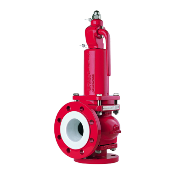
Series KSE/F, KSE-C/F
Safety Valves
with cerification
spring-loaded
Keep for future use!
This operating manual must be strictly observed before
transport, installation, operation and maintenance
Subject to change without notice.
Reproduction is generally permitted with indication of the source.
© Richter Chemie-Technik GmbH.
9530-001-en Revision 19 Edition 11/2018
Advertisement
Table of Contents

Subscribe to Our Youtube Channel
Related Manuals for Richter KSE/F Series


Summary of Contents for Richter KSE/F Series
- Page 1 Keep for future use! This operating manual must be strictly observed before transport, installation, operation and maintenance Subject to change without notice. Reproduction is generally permitted with indication of the source. © Richter Chemie-Technik GmbH. 9530-001-en Revision 19 Edition 11/2018...
-
Page 2: Table Of Contents
Series KSE/F, KSE-C/F Page List of Contents 7 Operation ..........15 List of Contents ......... 2 7.1 Initial commissioning ......... 15 Relevant documents ......... 3 7.2 Shutdown ..........15 1 Technical data ........3 7.3 Recommissioning ........15 1.1 Type plate, CE and body markings ..... 4 7.4 Improper operation and their consequences ............... -
Page 3: Relevant Documents
♦ VDTÜV data sheet "Safety valve 871" in German ♦ VDTÜV data sheet "Safety valve 100" in German ♦ Manufacturer Declaration TA-Luft ♦ Richter publication "Planning and using chemical ♦ Form for Safety Information Concerning the safety valves" in German... -
Page 4: Type Plate, Ce And Body Markings
Series KSE/F, KSE-C/F Page Type plate, CE and body = Narrowest flow Ø in mm (here: 40) (S)D/G = intended for discharging vapours/ markings gases (L)F = intended for discharging liquids The stainless steel name plate is undetachably riveted to the body. αw = Certified coefficient of discharge (here: 0.82 for (S)D/G and 0.55 for (L)F) -
Page 5: Pressure-Temperature Diagram
Series KSE/F, KSE-C/F Page Screws body / spring bonnet Hex. socket screws 914/1 of the bellows gasket Valve type screws Tightening torque Valve type screws Tightening torque [Nm] [in-lbs] [Nm] [in-lbs] KSE 25/50 4 x M12 KSE 25/50 4 x M8 KSE 50/80 4 x M12 KSE 50/80... -
Page 6: Safety
(plastic lining and plastic components). Intended use Improper operation Richter safety valves of the series KSE/F and KSE- C/F are pressure-maintaining components with safety The operational safety of the valve supplied is only function in accordance with the Pressure Equipment... -
Page 7: Safety Notes For Applications In Potentially Explosive Areas Based On The Directive 2014/34/ Ec (Atex)
Series KSE/F, KSE-C/F Page Safety notes for applications in potentially explosive areas based on the Directive 2014/34/ EC (ATEX) The valves are intended for use in a potentially must be excluded by superimposing a layer of inert explosive area and are therefore subject to the gas. -
Page 8: Safety Note For Valves, Certified To Clean Air Act (Ta Luft)
Series KSE/F, KSE-C/F Page ♦ The valve must be grounded. ♦ Plastic-lined valves must not be operated with carbon disulphide. This can be achieved in the simplest way via the pipe screws using tooth lock washers. Otherwise grounding must be ensured by different measures e.g. -
Page 9: Transport Securing For Kse-C/F
Series KSE/F, KSE-C/F Page Transport securing Return consignments for KSE-C/F Valves which have conveyed aggressive or toxic media rinse and clean before being The threaded rod is screwed through the inlet nozzle returned to the manufacturer's works. into the plug. It is inserted through the central bore of It is imperative to enclose a safety information the flange cover and screwed against the inlet flange sheet / general safety certificate on the field of... -
Page 10: Installation
KSE series". Detailed instructions for calculating the supply and The admissible pressure loss in the inlet line blow-off line are contained in the Richter publication must not exceed 3% of the set pressure of "Planning and implementing chemical safety valves". -
Page 11: Discharge Conditions And Reaction Forces
Fig. 5 absorbed. Instructions for calculating the reaction forces are contained in the Richter publication "Plan and install safety valves". Grounding The valve must be grounded. This can be achieved in Valve connecting dimensions the simplest way via the pipe screws using tooth lock washers. -
Page 12: Installation
Series KSE/F, KSE-C/F Page Installation DN 100/150 DN 80/100 ♦ The plant components to be protected are to be cleaned thoroughly prior to installation of the valve. ♦ Solids jeopardise the soft-sealing, high-precision surfaces of the seat and plug and permanent leaks could arise. -
Page 13: Design For Heavily Permeating Media (Option)
Series KSE/F, KSE-C/F Page DN 25/50, 50/80, 80/100 6.11 Design for heavily permeating media (Option) Spindle 802, insert sleeve 308, cylindrical pin 561/1, pressure ring 124, bearing guide 305 and adjusting screw 538 are made of HC-4. See sectional drawing in sections 9.2 and 9.3. -
Page 14: Shortened Or No Lifting Lever (Option)
Series KSE/F, KSE-C/F Page 6.12 Shortened or no lifting lever 6.13 Travel stop (Option) (Option) In order to exclude unauthorised activation, ♦ the lifting lever 238 can be shortened; a lever is supplied loose. See Fig. 13. ♦ the valve can be without a lifting lever; the locking plate 539 is not bored. -
Page 15: Operation
Series KSE/F, KSE-C/F Page Operation Initial commissioning Improper operation and their consequences Normally, the valves have been tested for leaks with air or water. Unless otherwise agreed there could be residual amounts of water in the flow section of the valve. This could result in a possible reaction with the medium. -
Page 16: Malfunctions
Series KSE/F, KSE-C/F Page Malfunctions ♦ Safety valve is leaking ♦ Flange connection ball valve/pipe is leaking Is there foreign matter between the seat and plug? Check the torque of the pipe screws with a torque wrench. (see Section 1.3) If tightness is not Is there any wear or damage to the seat or plug? achieved, the recommended torque may be ex- Have the nuts at the inlet nozzle been unevenly... -
Page 17: Maintenance
Series KSE/F, KSE-C/F Page Maintenance Safety valves must checked Screw connections operability at regular intervals according to the national regulations (in Germany: UVV - ♦ To prevent leaks, a regular check of the connec- pressure vessels, VBG 17 § 32 and TRD tion screws should be made in line with the operat- 601 sheet 2, paragraph 3.4). -
Page 18: Important Notes On Dismantling / Installation
Series KSE/F, KSE-C/F Page ♦ Screw on lifting cap 535 and tighten. ♦ Screw the stem nut 534 against the distance sleeve. The plug 204 is lifted off the seat 205 and ♦ Insert lifting lever 238. the closing force becomes ineffective. ♦... -
Page 19: Installation Of The Thrust Ring
Series KSE/F, KSE-C/F Page ♦ Tighten the hex. socket screws 914/1 for the bellows seal evenly in line with the tightening Do not turn the entire stem 802! There torques is a risk of the folds in the bellows 206 or ♦... -
Page 20: Kse-C/F 80/100, 100/150
Series KSE/F, KSE-C/F Page ♦ Press the bellows collar out of the guide of the ♦ Mount a hex. nut on the free end of the spindle so thrust flanges and then screw the bellows 206 off that when the complete unit is raised the internals the spindle 802. - Page 21 Series KSE/F, KSE-C/F Page ♦ This must be raised further until the distance ♦ Assemble the entire upper section with the body between the upper edge of the insert sleeve and 100. Tighten the hex. nuts 920/2 and hex. socket the edge of the stem guide is approx.
-
Page 22: Tests
Series KSE/F, KSE-C/F Page Tests 9.9.2 Test pressure This test should take place on a test bench Following the assembly of the valve, the stroke and with a neutral medium such as air or water. the test pressure must be checked. Regarding their suitability and precision, the pressure gauges must conform to the requirements of current national regulations... -
Page 23: Drawings
Series KSE/F, KSE-C/F Page Drawings 10.1 Legend Body Option blocking screw (see section 6.8) thrust flange 901/3 Hex. screw inlet nozzle 918/1 threaded rod pressure ring 927/1B cap nut plug 929/2 prevailing torque type hex. nut Seat Option gas-tight design (see section 6.9) bellows lifting lever lifting aid... -
Page 24: Sectional Drawing Kse/F
Series KSE/F, KSE-C/F Page 10.2 Sectional drawing KSE/F 9530-001-en Revision 19 TM 9549 Edition 11/2018... -
Page 25: Sectional Drawing Kse-C/F
Series KSE/F, KSE-C/F Page 10.3 Sectional drawing KSE-C/F DN 80/100, 100/150 9530-001-en Revision 19 TM 9549 Edition 11/2018... -
Page 26: Views
Series KSE/F, KSE-C/F Page 10.4 Views View X View X DN 100/150 Detail Y upper spring plate View W DN 100/150 Detail Z lower spring plate 9530-001-en Revision 19 TM 9549 Edition 11/2018... -
Page 27: Dimensional Drawing Kse/F And Kse-C/F
Series KSE/F, KSE-C/F Page 10.5 Dimensional drawing KSE/F and KSE-C/F Inlet Outlet Nominal size KSE-C 25/50 50/80 80/100 100/150 all dimensions in mm Flange connecting dimensions: DIN EN 1092-2, type B (ISO 7005-2, type B) PN 16 or flanges drilled to ASME 16.5 Class 150 9530-001-en Revision 19 TM 9549... - Page 31 Waste Management Law (AbfG) and the Water Resources Act (WHG) An inspection/repair of Richter products and parts will only take place, if the attached explanation is filled out cor- rectly and completely by authorized and qualified technical personnel and is available.
- Page 32 Safety Information / Declaration of No Objection Concerning the Contamination of Richter-Pumps, -Valves and Components SCOPE AND PURPOSE Each entrepreneur (operator) carries the responsibility for the health and safety of his employees. This extends also to the personnel, who implements repairs with the operator or with the contractor.
- Page 33 for credit note Phone : Fax : End user : A. Details of Richter-product: Failure description: Classification: Article number: Serial number: B. Condition of the Richter- product: Contamination : Was it in operation ? toxic ...
- Page 34 Fax: + 91 / 22 / 287 94 680 Email: RichterCedarFalls-Info@idexcorp.com Email: RichterMumbai-Info@idexcorp.com Internet: www.richter-inc.com Internet: www.richter-ct.com © Richter Chemie-Technik GmbH 2019 Edition 03/2020 Subject to change without notice. Revision 0,0 9530B001-en Richter™ = Richter Chemie-Technik GmbH; IDEX™ = IDEX Corporation...
Need help?
Do you have a question about the KSE/F Series and is the answer not in the manual?
Questions and answers