Table of Contents
Advertisement
Quick Links
INSTALLATION AND OPERATING MANUAL
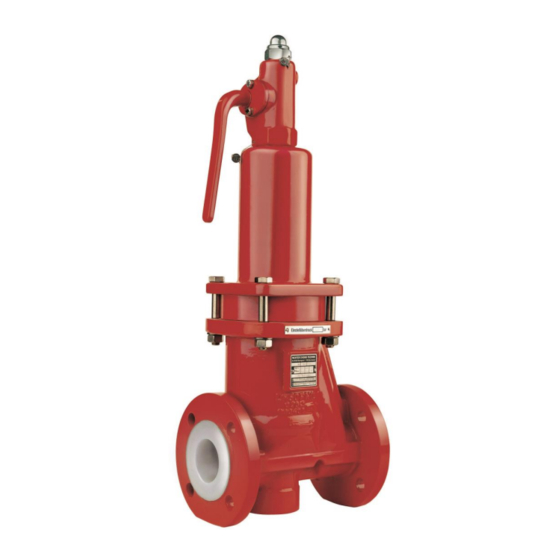
Series GU/F
Overflow and pressure relief valve
DN 25 with certification
spring-loaded
Keep for future use!
This operating manual must be strictly observed before
transport, installation, operation and maintenance
Subject to change without notice.
Reproduction is generally permitted with indication of the source.
© Richter Chemie-Technik GmbH.
9530-020-en Revision 15 Edition 05/2022
Advertisement
Table of Contents

Subscribe to Our Youtube Channel
Related Manuals for Richter GU/F Series


Summary of Contents for Richter GU/F Series
- Page 1 Keep for future use! This operating manual must be strictly observed before transport, installation, operation and maintenance Subject to change without notice. Reproduction is generally permitted with indication of the source. © Richter Chemie-Technik GmbH. 9530-020-en Revision 15 Edition 05/2022...
-
Page 2: Table Of Contents
Series GU/F Page List of Contents 6 Installation ..........9 List of Contents ......... 2 6.1 Sizing of the outlet line ........ 9 Relevant documents ......... 2 6.2 Sizing of the outlet line ......10 1 Technical data ........3 6.2.1 Admissible back pressure ...... -
Page 3: Technical Data
Series GU/F Page Technical data Manufacturer : Valve size in mm Richter Chemie-Technik GmbH DN 25, 40*, 50, 65, 80, in mm Otto-Schott-Str. 2 * Availability on request 1“, 1½“, 2“, 3“, in inches, Cl 150 D-47906 Kempen 1“, 1½“, 2“ in inches, Cl 300 on request... -
Page 4: Component Identification
Series GU/F Page Example plate test pressure Pipe screws, flanges to ISO/DIN Flange screws Tightening torque Nominal size [mm] [ISO/DIN] [Nm] [in-lbs] 4 x M12 Body identification : 4 x M16 The following are visible on the body according to DIN 4 x M16 EN 19 and AD 2000 A4: 4 x M16... -
Page 5: Screw-In Tool For Valve Seat
Series GU/F Page Hex. socket screws 914/1 of the bellows seal Pressure/temperature diagram Nominal size screws Tightening torque 2014/68/EU (PED), AD2000, DIN EN 16668 [mm] [ISO/DIN] [Nm] [in-lbs] 4 x M8 4 x M8 4 x M8 4 x M8 4 x M8 Screw-in tool for valve seat Nominal size... -
Page 6: Safety
Intended use The operational safety of the valve supplied is only guaranteed if it is used properly in accordance with Richter overflow valves of the GU series are pressure- Section 2.1 of this operating manual. maintaining components in accordance with the... -
Page 7: Safety Notes For Applications In Potentially Explosive Areas Based On The Directive 2014/34/ Ec (Atex)
Series GU/F Page Safety notes for applications in potentially explosive areas based on the Directive 2014/34/ EC (ATEX) The valves are intended for use in a potentially must be excluded by superimposing a layer of inert explosive area and are therefore subject to the gas. -
Page 8: Safety Note For Valves, Certified To Clean Air Act (Ta-Luft)
Series GU/F Page Safety note for valves, certified to Clean Air Act (TA-Luft) ♦ Carry out regular maintenance intervals and check Certificate / Manufacturer Declaration Validity is dependent on the operating instructions being read the tightness of the screw connections and tighten and observed. -
Page 9: Storage
Series GU/F Page Storage Disposal If the valve is not installed immediately after delivery, Parts of the valve may be contaminated with medium it must be put into proper storage. which is detrimental to health and the environment and therefore cleaning is not sufficient. It should be stored in a dry, vibration-free and well- ventilated room at as constant a temperature as Risk of personal injury or damage to the... -
Page 10: Sizing Of The Outlet Line
Instructions for calculating the reaction forces are contained in the Richter publication "Plan and install overflow valves". Valve connecting dimensions main dimensions contained dimensional drawing in Section 10.5. -
Page 11: Flange Caps And Gaskets
Otherwise grounding must be ensured by different PTFE-lined seals with a metal inlay. measures e.g. a cable link. These gaskets are available as special accessories in the Richter range. Installation Direction of flow and ♦ The plant components to be protected are to be installation position cleaned thoroughly prior to installation of the valve. -
Page 12: Signal Transmitter (Option)
Series GU/F Page Signal transmitter (Option) On request, an signal transmitter is available for remote monitoring. ♦ Glue in stem extension 805 (e.g. Loctite 638) and secure with a hex. nut 920/4. ♦ The support, lower part, 542 is screwed on instead of the cap nut 927/1. -
Page 13: Operation
Series GU/F Page Operation Initial commissioning Improper operation and their consequences Normally, the valves have been tested for leaks with air or water. Unless otherwise agreed there could be residual amounts of water in the flow section of the valve. This could result in a possible reaction with the medium. -
Page 14: Malfunctions
Series GU/F Page Malfunctions ♦ Overflow valve is leaking The cause of cracked bellows could have been, for Is there foreign matter between the seat and plug? example, an inadmissibly high back pressure during operation of the overflow valve. Dismantle Is there any wear or damage to the seat or plug? the overflow valve and have it repaired. -
Page 15: Maintenance
Series GU/F Page Maintenance Overflow valves must be checked for Modification of the overflow operability at regular intervals according to valve the national regulations (in Germany: UVV - pressure vessels, VBG 17 § 32 and TRD If modifications to the valve are required, the 601 sheet 2, paragraph 3.4). -
Page 16: Replacement Of Components
Series GU/F Page ♦ Undo the hex. socket screws 914/1. Centre the Replacement of components spring bonnet 513 with internals on the body 100. Ensure that there is metallic contact between the 9.6.1 Dismantling of the plug body and the spring bonnet. Then tighten the screws 901/1, 936/1, 936/2 and 920/2. -
Page 17: Test Pressure
Series GU/F Page ♦ It is recommended to perform a bubble test with a 9.7.2 Test pressure 5 mm diameter hose positioned 5 mm below the surface of water. The other end of the hose is This test should take place on a test bench sealed to the outlet of the valve by means of a with a neutral medium such as air or water. -
Page 18: Sectional Drawing
Series GU/F Page 10.2 Sectional drawing 9530-020-en Revision 15 TM 10477 Edition 05/2022... -
Page 19: Views
Series GU/F Page 10.3 Views View X Detail Y upper spring plate Detail Z lower spring plate 9530-020-en Revision 15 TM 10477 Edition 05/2022... -
Page 20: Dimensional Drawing
Series GU/F Page 10.4 Dimensional drawing DIN EN 558-1 ANSI/ISA-75.08.01 ANSI/ISA-75.08.01 Nominal series 1 Class 150 Class 300 size inch inch inch 1“ 7.24 7.76 1½“ 8.70 9.25 2“ 10.00 10.50 2½“ 3“ 12.20 Flange connecting dimensions: Flanges acc. to DIN EN 1092-2, type B (ISO 7005-2 Type B) PN 16 or flanges drilled to ASME B16.5 Class 150 Flanges acc. - Page 25 Waste Management Law (AbfG) and the Water Resources Act (WHG) An inspection/repair of Richter products and parts will only take place, if the attached explanation is filled out cor- rectly and completely by authorized and qualified technical personnel and is available.
- Page 26 Safety Information / Declaration of No Objection Concerning the Contamination of Richter-Pumps, -Valves and Components SCOPE AND PURPOSE Each entrepreneur (operator) carries the responsibility for the health and safety of his employees. This extends also to the personnel, who implements repairs with the operator or with the contractor.
- Page 27 for credit note Phone : Fax : End user : A. Details of Richter-product: Failure description: Classification: Article number: Serial number: B. Condition of the Richter- product: Contamination : Was it in operation ? toxic ...
- Page 28 Email: RichterCedarFalls-Info@idexcorp.com Email: RichterMumbai-Info@idexcorp.com Internet: www.richter-inc.com Internet: www.richter-ct.com © Richter Chemie-Technik GmbH 2022 Edition 09/2022 Revision 2.0 Subject to change without notice. 9530B020-en These installation and operating instructions must be kept! Richter™ = Richter Chemie-Technik GmbH; IDEX™ = IDEX Corporation...
Need help?
Do you have a question about the GU/F Series and is the answer not in the manual?
Questions and answers