Table of Contents
Advertisement
Quick Links
INSTALLATION AND OPERATING MANUAL
Series KN/F, KNP/F
KN-D/F, KNP-D/F
KN-S/F, KNP-S/F
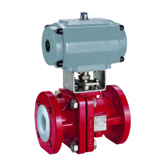
Ball Valve
with ball/stem unit or
Al
O
ball / stem and
2
3
Richter ENVIPACK universal packing
Keep for future use!
This operating manual must be strictly observed before
transport, installation, operation and maintenance
Subject to change without notice.
Reproduction is generally permitted with indication of the source.
© Richter Chemie-Technik GmbH.
9520-050-en Revision 18 Edition 11/2018
Advertisement
Table of Contents

Subscribe to Our Youtube Channel
Related Manuals for Richter KN/F Series


Summary of Contents for Richter KN/F Series
- Page 1 KN-D/F, KNP-D/F KN-S/F, KNP-S/F Ball Valve with ball/stem unit or ball / stem and Richter ENVIPACK universal packing Keep for future use! This operating manual must be strictly observed before transport, installation, operation and maintenance Subject to change without notice.
-
Page 2: Table Of Contents
Series KN/F, KNP/F, KN-D/F, KNP-D/F Page 2 List of Contents List of Contents ......... 2 8 Malfunctions ........11 Relevant documents ......... 3 9 Maintenance ........12 1 Technical data ........3 9.1 Dismantling ball valve with ball/stem unit ............12 1.1 Type plate, CE and body markings .. -
Page 3: Relevant Documents
Temperature range : Ball valve with ball/stem unit or Al -ball / stem and See pressure-temperature diagram in Chapter 1.6. Richter ENVIPACK universal selfadjusting packing, two-piece body. Operating pressure: DN 15 - DN 100 from vacuum to 16 bar (PN16) Series: DN 150 - 200 max. -
Page 4: Type Plate, Ce And Body Markings
Ball/stem unit -ball Stem Nominal size Article No. [mm] [inch] Options : ♦ Richter ENVIPACK. double packing bonnet 8“ 9599-41-8310 for particularly high safety requirements, selfadjusting. ♦ monitoring or flushing connection Please contact Richter to ♦ stem unit extension order the mounting sleeve. -
Page 5: Actuating Torques
Series KN/F, KNP/F, KN-D/F, KNP-D/F Page 5 Body screws -ball Nominal size screws Tightening torque Δp in bar [mm] [ISO/DIN] [Nm] [in-lbs] ≤ 3 max. adm. 4 x M12 [mm] [Nm] [Nm] [Nm] [Nm] [Nm] 4 x M12 4 x M12 4 x M16 4 x M16 8 x M16... -
Page 6: Pressure-Temperature Diagram
Series KN/F, KNP/F, KN-D/F, KNP-D/F Page 6 Pressure-temperature diagram When used in the minus temperature range, the regulations applicable in the country in question must be observed. -ball Stem unit 9520-050-en Revision 18 TM 9818 Edition 11/2018... -
Page 7: Notes On Safety
Intended use Ball valves are on/off valves. Richter ball valves are pressure containing compo- nents in accordance with the Pressure Equipment Directive (PED) for the passage and shut-off of fluids. The valves are suitable for vapours, gases and non- boiling liquids of group 1 according to the PED and have a corrosion-resistant plastic lining. -
Page 8: Safety Notes For Applications In Potentially Explosive Areas Based On The Directive 2014/34/ Ec (Atex)
Series KN/F, KNP/F, KN-D/F, KNP-D/F Page 8 Safety notes for applications in potentially explosive areas based on the Directive 2014/34/ EC (ATEX) The valves are intended for use in a potentially 1. Chargeable liquid and non-conductive lining explosive area and are therefore subject to the Charges can occur on the lining surface. -
Page 9: Safety Note For Valves, Certified To Clean Air Act (Ta Luft)
Series KN/F, KNP/F, KN-D/F, KNP-D/F Page 9 ♦ Actuators and electric peripherals, such as ♦ Attachments such as actuators, position control- temperature, pressure and flow sensors etc., must lers, limit switches etc. must satisfy the relevant comply with the valid safety requirements and safety regulations as regards explosion protection explosion protection provisions. -
Page 10: Installation
PTFE-lined seals with a metal inlay. These gaskets are available as special accessories in This can be achieved in the simplest way via the pipe the Richter range. screws using tooth lock washers. A toothed lock washer is placed underneath each pipe screw per Direction of flow and flange. -
Page 11: Operation
Series KN/F, KNP/F, KN-D/F, KNP-D/F Page 11 Operation Initial commissioning ♦ Increased wear occurs in operation with solids contents. ♦ Operation during cavitation leads to increased Normally, the valves have been tested for leaks with wear. air or water. Prior to initial operation check cover ♦... -
Page 12: Maintenance
Series KN/F, KNP/F, KN-D/F, KNP-D/F Page 12 Maintenance ♦ All repair work is to be performed by qualified 9.1.3 Ball valve with actuator personnel using the appropriate tools. ♦ For the arrangement, designation and item ♦ Remove actuator 850 and coupling 804. numbers of all parts of the valve, see section 10. -
Page 13: Packing Bellows
Series KN/F, KNP/F, KN-D/F, KNP-D/F Page 13 9.2.1 Packing bellows 9.3.2 Packing bellows ♦ Press thrust ring 405/1 into packing bellows 403. ♦ Remove lever 203. ♦ Install retaining washer 526 (not in DN 150, ♦ Dismantle packing gland follower 503 and spring 200/150 and 200). -
Page 14: Packing Bellows
Series KN/F, KNP/F, KN-D/F, KNP-D/F Page 14 9.4.1 Packing bellows Conversion from lever to actuator ♦ Press thrust ring 405/1 into packing bellows 403. ♦ Install retaining washer 526. (not in DN 150 and ♦ Select the actuator in accordance with the 200/150) instructions of the actuator manufacturer. -
Page 15: Drawings
Series KN/F, KNP/F, KN-D/F, KNP-D/F Page 15 Drawings 10.1 Legend main body includes: Ring (Option) body end piece pressure spring ball 980/1 round head grooved pin actuator ball/stem unit gear stem 901/1 Hex. screw lever (DN 25, 40, 50) seat ring 901/x hex. -
Page 16: Sectional Drawings Ball Valve
Series KN/F, KNP/F, KN-D/F, KNP-D/F Page 16 10.2 Sectional drawings ball valve Ball valve with ball/stem unit and lever DN 15 – DN 200/150 Holes of the flange- and housing screws view displaced by 45°. 9520-050-en Revision 18 TM 9818 Edition 11/2018... - Page 17 Series KN/F, KNP/F, KN-D/F, KNP-D/F Page 17 Ball valve with ball/stem unit and worm gear DN 200 9520-050-en Revision 18 TM 9818 Edition 11/2018...
-
Page 18: Sectional Drawing Ball Valve And Actuator
Series KN/F, KNP/F, KN-D/F, KNP-D/F Page 18 10.3 Sectional drawing ball valve and actuator Ball valve with ball/stem unit and actuator DN 15 – DN 200 Holes of the flange- and housing screws view displaced by 45°. 9520-050-en Revision 18 TM 9818 Edition 11/2018... -
Page 19: Sectional Drawing Ball Valve With Ball, Stem And Lever
Series KN/F, KNP/F, KN-D/F, KNP-D/F Page 19 10.4 Sectional drawing ball valve with ball, stem and lever DN 15 – DN 200/150 Holes of the flange- and housing screws view displaced by 45°. 9520-050-en Revision 18 TM 9818 Edition 11/2018... -
Page 20: Sectional Drawing Ball Valve With Ball, Stem And Actuator
Series KN/F, KNP/F, KN-D/F, KNP-D/F Page 20 10.5 Sectional drawing ball valve with ball, stem and actuator DN 15 – DN 200/150 Holes of the flange- and housing screws view displaced by 45°. 9520-050-en Revision 18 TM 9818 Edition 11/2018... -
Page 21: View And Section Ball Valve With Lever
Series KN/F, KNP/F, KN-D/F, KNP-D/F Page 21 10.6 View and section ball valve with lever View Z Section B – B 10.7 Sections ball valve with actuator Section A – A Section B – B 9520-050-en Revision 18 TM 9818 Edition 11/2018... -
Page 22: Dimensional Drawing Ball Valve
Series KN/F, KNP/F, KN-D/F, KNP-D/F Page 22 10.8 Dimensional drawing ball valve Ball valve with ball/stem unit and lever DN 15 – DN 200/150 200/150 223.5 512.5 DN 200/150 mit reduziertem Durchgang DN 150 all dimensions in mm a worm gear is recommended instead of the hand lever. DN 150 and DN 200/150: At Δp >... - Page 23 Series KN/F, KNP/F, KN-D/F, KNP-D/F Page 23 Ball valve with ball/stem unit and worm gear DN 200 9520-050-en Revision 18 TM 9818 Edition 11/2018...
-
Page 24: Dimensional Drawing Ball Valve With Actuator
Series KN/F, KNP/F, KN-D/F, KNP-D/F Page 24 10.9 Dimensional drawing ball valve with actuator 200/150 223.5 228.5 Connection ISO 5211 9520-050-en Revision 18 TM 9818 Edition 11/2018... - Page 25 Series KN/F, KNP/F, KN-D/F, KNP-D/F Page 25 DN 200/150 with reduced bore DN 150 H2 = 80 mm if F10 or F12 on the actuator side Dimensions L1, L2, L3, H3 and H4 vary depending on the actuator manufacturer. all dimensions in mm DIN EN 1092-2, Form B (ISO 7005-2, Form B) Flanges drilled acc.
- Page 29 A Unit of IDEX Corporation Kempen, 27.01.2011 Declaration by the Manufacturer Functional Safety according to IEC 61508 We declare, that the devices KN, KNR, KNA, KNAR, KNP, KNRP, KNAP, KNARP are suitable for use in a safety related application, if the safety instructions and the following parameters are observed: Device Type: Proof Test Interval:...
- Page 30 Safety Information / Declaration of No Objection Concerning the Contamination of Richter-Pumps, -Valves and Components SCOPE AND PURPOSE Each entrepreneur (operator) carries the responsibility for the health and safety of his employees. This extends also to the personnel, who implements repairs with the operator or with the contractor.
- Page 31 Contact person : Phone : Fax : End user : A. Details of Richter-product: Failure description: Classification: Article number: Serial number: B. Condition of the Richter-product: Contamination : □ □ □ □ Was it in operation ? toxic □ □...
- Page 32 Waste Management Law (AbfG) and the Water Resources Act (WHG) An inspection/repair of Richter products and parts will only take place, if the attached explanation is filled out correctly and completely by authorized and qualified technical personnel and is available.
- Page 36 Edition 11/2017 Revision 17 9520-050-en EST. JOHANNESBURG South Africa: 1986 Tel: 011 397 2833 0861 103 103 DURBAN E-mail: sales@valve.co.za www.valve.co.za Tel: 031 579 2593 SCAN ME...
Need help?
Do you have a question about the KN/F Series and is the answer not in the manual?
Questions and answers