Table of Contents
Advertisement
Quick Links
INSTALLATION AND OPERATING MANUAL
Series KA-N/F, KAP-N/F
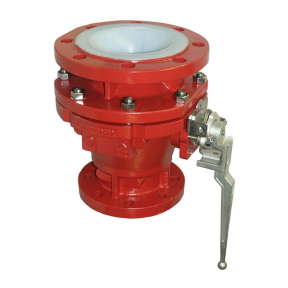
Bottom drain ball valve
with ball/stem unit or Al
O
ball / stem and
2
3
Richter ENVIPACK
universal packing
Keep for future use!
This operating manual must be strictly observed before
transport, installation, operation and maintenance
Subject to change without notice.
Reproduction is generally permitted with indication of the source.
© Richter Chemie-Technik GmbH.
9520-017-en Revision 15 Edition 05/2022
Advertisement
Table of Contents

Related Manuals for Richter KA-N/F Series


Summary of Contents for Richter KA-N/F Series
- Page 1 Keep for future use! This operating manual must be strictly observed before transport, installation, operation and maintenance Subject to change without notice. Reproduction is generally permitted with indication of the source. © Richter Chemie-Technik GmbH. 9520-017-en Revision 15 Edition 05/2022...
-
Page 2: Table Of Contents
Series KA-N/F, KAP-N/F Page 2 List of Contents 8 Malfunctions ........11 List of Contents ......... 2 9 Maintenance ........12 Relevant documents ......... 3 9.1 Dismantling KA-N/F with ball/stem unit ..12 1 Technical data ........3 9.1.1 KA-N/F with lever .......... 12 1.1 Type plate, CE and body markings ..... -
Page 3: Relevant Documents
Ball valve sizes in mm: Internet: http://www.richter-ct.com DN 50/25, 80/50, 100/50, 150/100 Designation : Weight, KA-N/F manually operated: Bottom drain ball valve with ball/stem unit or ball / stem and Richter ENVIPACK self-adjusting universal Nom. 50/25 80/50 100/50 150/100 size stuffing box, two-piece housing. -
Page 4: Type Plate, Ce And Body Markings
Series KA-N/F, KAP-N/F Page 4 Tightening torques Options : ♦ Richter ENVIPACK double packing All screws greased, tighten in diametrically particularly high safety requirements, opposite sequence! selfadjusting. The tightening torques for pipe screws and body On request, monitoring and flushing connection. -
Page 5: Actuating Torques - Ball/Stem Unit
Series KA-N/F, KAP-N/F Page 5 Actuating torques - ball/stem Pressure-temperature diagram unit When used in the minus temperature range, the reg Test medium: water 20 °C Higher actuating torques may occur with other media. ulations applicable in the country in question Δp in bar must be observed. -
Page 6: Notes On Safety
Intended use Ball valves are on/off valves. Richter bottom drain ball valves series KA-N/F / KAPN/F are pressure containing components in accordance with the Pressure Equipment Directive (PED) for the passage and shut-off of fluids. The valves are suitable for vapours, gases and non- boiling liquids of group 1 according to the PED and have a corrosion-resistant plastic lining. -
Page 7: Safety Notes For Applications In Potentially Explosive Areas Based On The Directive 2014/34/ Ec (Atex)
Series KA-N/F, KAP-N/F Page 7 Safety notes for applications in potentially explosive areas based on the Directive 2014/34/ EC (ATEX) The valves are intended for use in a potentially by superimposing a layer of nitrogen. It is recom- explosive area and are therefore subject to the mended to wait 1 hour before removing the valve conformity assessment procedure of the directive from the plant in order to permit the elimination of... -
Page 8: Safety Note For Valves, Certified To Clean Air Act (Ta Luft)
Series KA-N/F, KAP-N/F Page 8 comply with the valid safety requirements and safety regulations as regards explosion protection explosion protection provisions. and, if required, be designed in compliance with ATEX. ♦ The valve must be grounded. ♦ Special attention must be paid to the appropriate ♦... -
Page 9: Installation
If plastic sealing surfaces, e.g. on mating flanges made of metal or enamel, can be damaged, use PTFE-lined seals with a metal inlay. These gaskets are available as special accessories in the Richter range. Direction of flow and installa- tion position Grounding Installation is independent of the direction of flow. -
Page 10: Operation
Series KA-N/F, KAP-N/F Page 10 Operation ♦ If the ball blocks, do not apply force as the Initial commissioning ball/stem or ball/stem unit may break if the max. adm. torque is exceeded. Normally, the valves have been tested for leaks with ♦... -
Page 11: Malfunctions
Series KA-N/F, KAP-N/F Page 11 Malfunctions ♦ Flange connection valve/pipe is leaking ♦ The ball no longer closes completely Retighten the flange screws to a tightening torque Is the stem deformed? according to Section 1.2. If this does not remedy Is the coupling worn? the leak, the recommended torques may be ex- With a worm gear or actuator, check whether the... -
Page 12: Maintenance
Series KA-N/F, KAP-N/F Page 12 Maintenance ♦ All repair work is to be performed by qualified Dismantling KA-N/F with personnel using the appropriate tools. ball/stem ♦ For the arrangement, designation and item numbers of all parts of the valve, see Section It is possible with a KA-N/F, KAP-N/F with ball and stem to replace the seat rings and ball without ♦... -
Page 13: Kap-N/F With Actuator
Series KA-N/F, KAP-N/F Page 13 9.2.4 KAP-N/F with actuator 9.3.3 KAP-N/F with actuator ♦ Mount actuator 850 with coupling 804. ♦ Mount spring gland follower 502 and packing gland ♦ Dismantle packing gland follower 503 and spring follower 503. Tighten packing nuts until there is no gap between packing gland follower and spring gland follower 502. -
Page 14: Kap-N/F With Actuator
Series KA-N/F, KAP-N/F Page 14 9.4.3 KAP-N/F with actuator Conversion from lever to actuator ♦ Mount spring gland follower 502 and packing gland follower 503. Tighten packing nuts until ♦ Select the actuator in accordance with the instruc- there is no gap between packing gland follower tions of the actuator manufacturer. -
Page 15: Sectional Drawing Ka-N/F With Ball/Stem Unit And Lever
Series KA-N/F, KAP-N/F Page 15 10.2 Sectional drawing KA-N/F with ball/stem unit and lever Holes view displaced by 45°. 9520-017-en Revision 15 TM 10477 Edition 05/2022... -
Page 16: Sectional Drawing Kap-N/F With Ball/Stem Unit And Actuator
Series KA-N/F, KAP-N/F Page 16 10.3 Sectional drawing KAP-N/F with ball/stem unit and actuator Holes view displaced by 45°. 9520-017-en Revision 15 TM 10477 Edition 05/2022... -
Page 17: Sectional Drawing Ka-N/F With Ball / Stem And Lever
Series KA-N/F, KAP-N/F Page 17 10.4 Sectional drawing KA-N/F with ball / stem and lever Holes view displaced by 45°. 9520-017-en Revision 15 TM 10477 Edition 05/2022... -
Page 18: Sectional Drawing Kap-N/F With Ball / Stem And Actuator
Series KA-N/F, KAP-N/F Page 18 10.5 Sectional drawing KAP-N/F with ball / stem and actuator Holes view displaced by 45°. 9520-017-en Revision 15 TM 10477 Edition 05/2022... -
Page 19: View And Section Ka-N/F
Series KA-N/F, KAP-N/F Page 19 10.6 View and section KA-N/F 10.7 Sections KAP-N/F 9520-017-en Revision 15 TM 10477 Edition 05/2022... -
Page 20: Dimensional Drawing Ka-N/F
Series KA-N/F, KAP-N/F Page 20 10.8 Dimensional drawing KA-N/F DN/DN1 50/25 80/50 100/50 150/100 all dimensions in mm Flange connecting dimensions: DIN EN 1092-2, type B (ISO 7005-2, type B) PN 16 or flanges drilled to ASME 16.5 Class 150 9520-017-en Revision 15 TM 10477... -
Page 21: Dimensional Drawing Kap-N/F
Series KA-N/F, KAP-N/F Page 21 10.9 Dimensional drawing KAP-N/F Connecting DN/DN1 dimensions to DIN/ISO 5211 50/25 80/50 100/50 150/100 all dimensions in mm Dimensions L1, L2, L3, H3 and H4 vary depending on the actuator manufacturer. Flange connecting dimensions: DIN EN 1092-2, type B (ISO 7005-2, type B) PN 16 or flanges drilled to ASME 16.5 Class 150 9520-017-en Revision 15 TM 10477... - Page 26 Waste Management Law (AbfG) and the Water Resources Act (WHG) An inspection/repair of Richter products and parts will only take place, if the attached explanation is filled out cor- rectly and completely by authorized and qualified technical personnel and is available.
- Page 27 Safety Information / Declaration of No Objection Concerning the Contamination of Richter-Pumps, -Valves and Components SCOPE AND PURPOSE Each entrepreneur (operator) carries the responsibility for the health and safety of his employees. This extends also to the personnel, who implements repairs with the operator or with the contractor.
- Page 28 for credit note Phone : Fax : End user : A. Details of Richter-product: Failure description: Classification: Article number: Serial number: B. Condition of the Richter- product: Contamination : Was it in operation ? toxic ...
- Page 29 Email: RichterCedarFalls-Info@idexcorp.com Email: RichterMumbai-Info@idexcorp.com Internet: www.richter-inc.com Internet: www.richter-ct.com © Richter Chemie-Technik GmbH 2022 Edition 09/2022 Revision 2.0 Subject to change without notice. 9520B017-en These installation and operating instructions must be kept! Richter™ = Richter Chemie-Technik GmbH; IDEX™ = IDEX Corporation...
Need help?
Do you have a question about the KA-N/F Series and is the answer not in the manual?
Questions and answers