Table of Contents
Advertisement
Quick Links
INSTALLATION AND OPERATING MANUAL
Series KN/F, KNP/F, KN-D/F, KNP-D/F
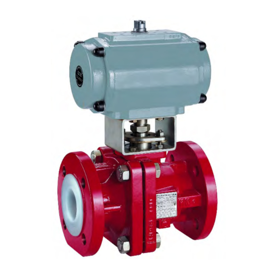
Ball Valve
with ball/stem unit or
Al
O
ball / stem and
2
3
Richter ENVIPACK universal packing
Keep for future use!
This operating manual must be strictly observed before
transport, installation, operation and maintenance
Subject to change without notice.
Reproduction is generally permitted with indication of the source.
© Richter Chemie-Technik GmbH
9520-050-en Revision 13 Edition 07/2015
Advertisement
Table of Contents

Subscribe to Our Youtube Channel
Related Manuals for Richter KN/F Series


Summary of Contents for Richter KN/F Series
- Page 1 Series KN/F, KNP/F, KN-D/F, KNP-D/F Ball Valve with ball/stem unit or ball / stem and Richter ENVIPACK universal packing Keep for future use! This operating manual must be strictly observed before transport, installation, operation and maintenance Subject to change without notice.
-
Page 2: Table Of Contents
Series KN/F, KNP/F, KN-D/F, KNP-D/F Page 2 List of Contents 9 Maintenance ........12 List of Contents ......... 2 9.1 Dismantling ball valve with ball/stem unit . 12 Relevant documents ......... 3 9.1.1 Ball valve with lever ........12 1 Technical data ........3 9.1.2 Packing bellows .......... -
Page 3: Relevant Documents
See pressure-temperature diagram in Chapter 1.6. Designation: Operating pressure: Ball valve with ball/stem unit or Al -ball / stem and Richter ENVIPACK universal selfadjusting packing, DN 15 - DN 100 from vacuum to 16 bar (PN16) two-piece body. DN 150, 200 max. -
Page 4: Name Plate, Ce And Body Markings
Ball/stem unit -ball Nom. size Stem Article No. Options: [mm] [inch] Richter ENVIPACK double packing 8“ 9599-41-8310 for particularly high safety requirements, self- adjusting. On request, monitoring and flushing connection. Please contact Richter to order Ball/stem unit extension the mounting sleeve. -
Page 5: Breakaway Torques
Series KN/F, KNP/F, KN-D/F, KNP-D/F Page 5 Pipe screws, flanges ISO/DIN drilled to ASME Breakaway torques Class 150 Test medium: water 20 C Flange Screws Tightening torque Higher breakaway torques may occur with other nom. size media. [mm] [inch] [ASME] [in-lbs] [Nm] 4 x ½“... -
Page 6: Flow Values
Series KN/F, KNP/F, KN-D/F, KNP-D/F Page 6 Flow values Pressure-temperature-diagram Nennweite Kv100 When used in the temperature range below [mm] [US gpm] zero, the regulations applicable in the 17,5 respective countries must be observed. A special core material is used for the ball/stem unit for operating limits under –10 °C to –60 °C. -
Page 7: Notes On Safety
Chapter 2.1 of this operating manual. operation limits specified Ball valves are on/off valves. identification plate and in the pressure- Richter ball valves are pressure containing compo- temperature diagram must under nents in accordance with the Pressure Equipment circumstances be exceeded. -
Page 8: Safety Notes For Applications In Potentially Explosive Areas Based On The Directive 94/9/ Ec (Atex)
Series KN/F, KNP/F, KN-D/F, KNP-D/F Page 8 Safety notes for applications in potentially explosive areas based on the Directive 94/9/ EC (ATEX) The valves are intended for use in a potentially It is recommended to wait 1 hour before removing explosive area and are therefore subject to the the valve from the plant in order to permit the conformity assessment procedure of the directive... -
Page 9: Safety Note For Valves, Certified To German Clean Air Act (Ta Luft)
Series KN/F, KNP/F, KN-D/F, KNP-D/F Page 9 Safety note for valves, certified to German Clean Air Act (TA Luft) Perform maintenance at regular intervals and Certificate / Manufacturer Declaration Validity is dependent on the operating instructions being read check the screw connections relevant to leak- and observed. -
Page 10: Installation
These are available as special accessories from the The valve must be grounded. Richter product range. The simplest solution is to use tooth lock washers which are placed under one pipe bolt of each flange. -
Page 11: Operation
Series KN/F, KNP/F, KN-D/F, KNP-D/F Page 11 Operation Operation with solids leads to increased wear. Initial commissioning Operating during cavitation leads to increased Normally, the valves have been tested for leaks with wear. air or water. Prior to initial operation check body ... -
Page 12: Maintenance
Series KN/F, KNP/F, KN-D/F, KNP-D/F Page 12 Maintenance All repair work is to be performed by qualified 9.1.2 Packing bellows personnel using the appropriate tools. Remove retaining washer 526. For the arrangement, designation and item Separate thrust ring 405/1 and packing bellows numbers of all parts of the valve, see Chapter 10. -
Page 13: Ball Valve With Lever
Series KN/F, KNP/F, KN-D/F, KNP-D/F Page 13 Dismantle packing gland follower 503 and spring 9.2.2 Ball valve with lever gland follower 502. Mount lever stop 577, spring gland follower 502 Remove grounding spring washer 557. (in DN 80, 100, 150, 200/150 and 200 are 2 ... -
Page 14: Ball Valve With Lever
Series KN/F, KNP/F, KN-D/F, KNP-D/F Page 14 9.4.2 Ball valve with lever Mount coupling 804 and actuator 850. Observe the actuator position in accordance with the actua- Mount lever stop 577, spring gland follower 502 tor operating manual. (in DN 80, 100, 150 and 200/150 are 2 spring ... -
Page 15: Sectional Drawings Ball Valve
Series KN/F, KNP/F, KN-D/F, KNP-D/F Page 15 10.2 Sectional drawings ball valve DN 15 – DN 200/150 10.2.1 Ball valve with ball/stem unit and lever Holes of the flange- and housing screws view displaced by 45° 9520-050-en Revision 13 TM 8782 Edition 07/2015... -
Page 16: Ball Valve With Ball/Stem Unit And Worm Gear Dn 200
Series KN/F, KNP/F, KN-D/F, KNP-D/F Page 16 10.2.2 Ball valve with ball/stem unit and worm gear DN 200 9520-050-en Revision 13 TM 8782 Edition 07/2015... -
Page 17: Ball Valve With Ball/Stem Unit And Actuator
Series KN/F, KNP/F, KN-D/F, KNP-D/F Page 17 10.2.3 Ball valve with ball/stem unit and actuator Holes of the flange and housing screws view displaced by 45° 9520-050-en Revision 13 TM 8782 Edition 07/2015... -
Page 18: Ball Valve With Ball, Stem And Lever Dn 15 - Dn 200/150
Series KN/F, KNP/F, KN-D/F, KNP-D/F Page 18 10.2.4 Ball valve with ball, stem and lever DN 15 – DN 200/150 turned by 90° Holes of the flange and housing screws view displaced by 45° 9520-050-en Revision 13 TM 8782 Edition 07/2015... -
Page 19: Sectional Drawing Ball Valve With Ball, Stem And Actuator
Series KN/F, KNP/F, KN-D/F, KNP-D/F Page 19 10.2.5 Sectional drawing ball valve with ball, stem and actuator DN 15 – DN 200/150 Holes of the flange and housing screws view displaced by 45° 9520-050-en Revision 13 TM 8782 Edition 07/2015... -
Page 20: View And Section Ball Valve With Lever
Series KN/F, KNP/F, KN-D/F, KNP-D/F Page 20 10.3 View and section ball valve with lever Section B – B View Z Tighten packing gland follower 503 until spring gland follower 502 is in contact without any gap 10.4 Sections ball valve with actuator Section A –... -
Page 21: Dimensional Drawing Ball Valve
Series KN/F, KNP/F, KN-D/F, KNP-D/F Page 21 10.5 Dimensional drawing ball valve 10.5.1 Ball valve with ball/stem unit and lever DN 15 – DN 200/150 200/150 223,5 512,5 DN 200/150 with reduced bore DN 150 All dimensions in mm. At Δp > approx. 2 bar a worm gear is recommended instead of the hand lever. DN 150 and DN 200/150: DN 200: Only with worm gear... -
Page 22: Ball Valve With Ball/Stem Unit And Worm Gear Dn 200
Series KN/F, KNP/F, KN-D/F, KNP-D/F Page 22 Ball valve with ball/stem unit and worm gear DN 200 9520-050-en Revision 13 TM 8782 Edition 07/2015... -
Page 23: Dimensional Drawing Ball Valve With Actuator
Series KN/F, KNP/F, KN-D/F, KNP-D/F Page 23 10.5.3 Dimensional drawing ball valve with actuator 200/150 223,5 228,5 Connection ISO 5211 9520-050-en Revision 13 TM 8782 Edition 07/2015... -
Page 24: Flange Connection Dimensions
Series KN/F, KNP/F, KN-D/F, KNP-D/F Page 24 DN 200/150 with reduced bore DN 150 H2 = 80 mm if F10 or F12 on the actuator side Dimensions H3, H4, L1, L2 and L3 vary depending on the actuator manufacturer. All dimensions in mm. 10.5.4 Flange connection dimensions DIN EN 1092-2, Form B (ISO 7005-2, Form B) Flanges drilled acc. - Page 25 Das Unternehmen Richter Chemie-Technik GmbH bescheinigt hiermit, dass die o.a. Baureihen die grundsätzlichen Anforderungen der aufgeführten Richtlinien und Normen erfüllt. Richter Chemie-Technik GmbH confirms that the basic requirements of the above specified directives and standards have been fulfilled. Für nicht aufgeführte Nennweiten ist eine Kennzeichnung nicht zulässig.
- Page 26 A Unit of IDX Corporation Herstellererklärung / Manufacturer´s Declaration TA-Luft / German Clean Air Act (TA-Luft) Richter Kugelhahn / Richter Ball Valve Hiermit erklären wir, dass die Kugelhähne der Baureihen Hereby we declare, that the ball valves of the series KN, KNR, KNA, KNAR, KNB, KNBR, KNA-S;...
- Page 27 A Unit of IDEX Corporation Kempen, 27.01.2011 Declaration by the Manufacturer Functional Safety according to IEC 61508 We declare, that the devices KN, KNR, KNA, KNAR, KNP, KNRP, KNAP, KNARP are suitable for use in a safety related application, if the safety instructions and the following parameters are observed: Device Type: Proof Test Interval:...
- Page 28 Safety Information / Declaration of No Objection Concerning the Contamination of Richter-Pumps, -Valves and Components SCOPE AND PURPOSE Each entrepreneur (operator) carries the responsibility for the health and safety of his employees. This extends also to the personnel, who implements repairs with the operator or with the contractor.
- Page 29 A. Details of Richter-product: Failure description: Classification: Article number: Equipment: Serial number: Application tool: Application process: B. Condition of the Richter-product: Contamination : Was it in operation ? toxic Drained (product/operating supply item) ? caustic All openings hermetically locked! inflammable...
- Page 30 Waste Management Law (AbfG) and the Water Resources Act (WHG) An inspection/repair of Richter products and parts will only take place, if the attached explanation is filled out correctly and completely by authorized and qualified technical personnel and is available.
Need help?
Do you have a question about the KN/F Series and is the answer not in the manual?
Questions and answers