Table of Contents
Advertisement
Quick Links
INSTALLATION AND OPERATING MANUAL
Series NK/F, NKP/F, NKL/F, NKLP/F,
NKS/F, NKSP/F
Richter Shut-off and
Control Butterfly Valve
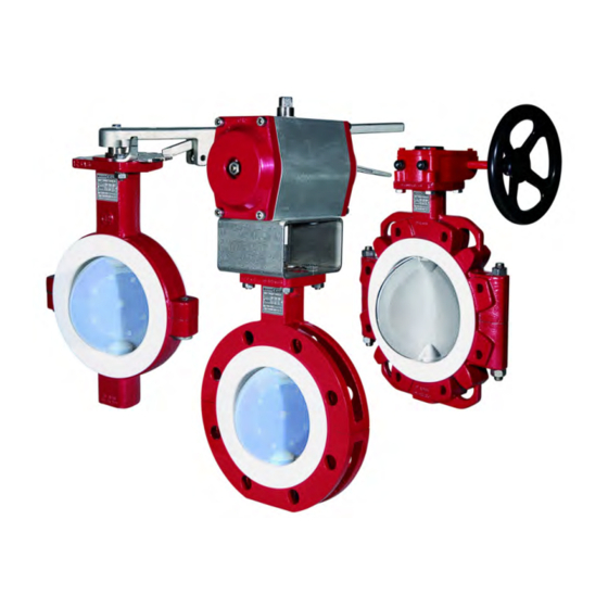
Lug-style body:
Wafer-style body:
Double-flange body: Series NK/F
Keep for future use!
This operating manual must be strictly observed before
transport, installation, operation and maintenance
Subject to change without notice.
Reproduction is generally permitted with indication of the source.
© Richter Chemie-Technik GmbH
9520-070-en Revision 10 Edition 10/2011
Series NKL/F
Series NKS/F
Advertisement
Table of Contents

Subscribe to Our Youtube Channel
Related Manuals for Richter NK/F series


Summary of Contents for Richter NK/F series
- Page 1 Keep for future use! This operating manual must be strictly observed before transport, installation, operation and maintenance Subject to change without notice. Reproduction is generally permitted with indication of the source. © Richter Chemie-Technik GmbH 9520-070-en Revision 10 Edition 10/2011...
-
Page 2: Table Of Contents
Series NK/F, NKP/F, NKS/F, NKSP/F, NKL/F, NKLP/F Page 2 List of Contents 8 Malfunctions ........14 List of Contents ......... 2 9 Maintenance ........14 Relevant documents ......... 3 9.1 Notes for assembly ........14 1 Technical data ........3 9.1.1 Safety stuffing box ........ -
Page 3: Relevant Documents
Contamination QM 0912-16-2001_en For NKLP/F, NKSP/F or NKP/F operating manual for actuator Technical data Materials: Manufacturer: Body material: Ductile cast iron EN-JS 1049 / Richter Chemie-Technik GmbH ASTM A395 Otto-Schott-Str. 2 D-47906 Kempen Lining material: PFA/PTFE .../F Telephone: +49 (0) 2152 146-0... -
Page 4: Overview Of Sizes
Series NK/F, NKP/F, NKS/F, NKSP/F, NKL/F, NKLP/F Page 4 Overview of sizes Series Actuation /F-L Body design DN 50, 80, 100, 150, 200 DN 50, 80, 100, 150, 200 Lever 2", 3", 4" 6, 8" 2", 3", 4" 6", 8" NK/F Gear DN 50, 80, 100, 150-300... -
Page 5: Tightening Torques
Series NK/F, NKP/F, NKS/F, NKSP/F, NKL/F, NKLP/F Page 5 Sign for transport securing device for actuator Pipe screws, flanges to ISO/DIN Flange Screws Tightening nom. size torque [mm] [ISO/DIN] [Nm] 4 x M16 8 x M16 8 x M16 8 x M20 8 x M20 12 x M20 12 x M20... -
Page 6: Dimensions - Installation
Series NK/F, NKP/F, NKS/F, NKSP/F, NKL/F, NKLP/F Page 6 Hex. socket screw 914/1 for sandwich body Hex. socket screw 914/1 for double-flange body Hex. socket Hex. socket Tightening Tightening Nom. size Nom. size torque torque screw screw [mm] [inch] [ISO/DIN] [mm] [inch] [mm]... -
Page 7: Weights (Ca. Kg)
Series NK/F, NKP/F, NKS/F, NKSP/F, NKL/F, NKLP/F Page 7 Weights (ca. kg) Sandwich- Double-flange Nom. size Lug style body body body open open open [mm] [inch] Lever Gear staff ende staff ende staff ende 2“ 3“ 4“ 6“ 16,0 11,0 12,0 8“... -
Page 8: Breakaway Torques
Intended use information which is to be observed during installation, operation and maintenance. Richter shut-off and control butterfly valves are It must therefore be read before installation and pressure-maintaining components in accordance with commissioning! the German Pressure Equipment Directive (DGRL) for For valves which are used in potentially explosive the passage and shut-off of fluids. -
Page 9: For The Customer / Operator
Series NK/F, NKP/F, NKS/F, NKSP/F, NKL/F, NKLP/F Page 9 Product features: the valve has been properly installed in the pipe system Wide sealing surfaces of the body lining the usual flow rates are not exceeded in continu- Long valve neck for optimum heat insulation ous operation. -
Page 10: Safety Note For Valves, Certified To German Clean Air Act (Ta Luft)
Series NK/F, NKP/F, NKS/F, NKSP/F, NKL/F, NKLP/F Page 10 If the valve is not completely filled with medium, If the valve is heated (e.g. heating jacket), it must e.g. during evacuation and filling, the formation of be ensured that the temperature classes pre- an explosive atmosphere must be prevented, e.g. -
Page 11: Storage
Series NK/F, NKP/F, NKS/F, NKSP/F, NKL/F, NKLP/F Page 11 Storage Transport securing device If the valve is not installed immediately after delivery, it must be put into proper storage. It should be stored in a dry, vibration-free and well- ventilated room at as constant a temperature as possible. -
Page 12: Installation
920/1 and a tooth lock washer 936/1 to the with a metal inlay should be used. These gaskets are underside of the head flange. available as special accessories in the Richter range. The other end is metallically secured in the plant. Series NK/F, NKP/F Butterfly valves with tapped bores are earthed by the pipe screws. -
Page 13: Operation
Series NK/F, NKP/F, NKS/F, NKSP/F, NKL/F, NKLP/F Page 13 Operation Initial commissioning Operation during cavitation leads to increased wear. Normally, the valves have been tested for leaks with Non-observance pressure-temperature air or water. Prior to initial operation check body diagram can lead to damage of the plastic lining. bolting. -
Page 14: Malfunctions
Series NK/F, NKP/F, NKS/F, NKSP/F, NKL/F, NKLP/F Page 14 Malfunctions Flange connection valve/pipe is leaking The ball no longer closes completely Retighten the flange screws to a tightening torque Is the stem deformed? according to Section 1.2. If this does not remedy Is the coupling worn? the leak, the recommended torques may be With a worm gear or actuator, check whether the... -
Page 15: Safety Stuffing Box
9.1.1 Safety stuffing box 9.2.3 Remotely actuated Insert sealing foil 413 between the upper and Richter butterfly valves can be remotely actuated by lower halve of the shell 120. means of pneumatic, hydraulic or electric quarter-turn actuators equipped with a connection as per ISO Displace packing rings 402/1 by 90°... -
Page 16: Proximity Switch
Tests respectively MSS SP-67. Following tests would be done after the assembly. For detailed installation and inspection regulations see QM No. 0910-08-1005, available from Richter on Measurement of the breakaway torque request. The breakaway torque required for opening and closing the valve is to be ascertained. The maximum torque should not exceed the values given in Section 1.8. -
Page 17: Sectional Drawing Nk/F, Dn 50 - 150, 2
Series NK/F, NKP/F, NKS/F, NKSP/F, NKL/F, NKLP/F Page 17 10.2 Sectional drawing NK/F, DN 50 – 150, 2"– 6" Double flange body, with lever assembly, disc/stem unit PFA-lined Only with option safety stuffing box. 9520-070-en Revision 10 TM 8361 Edition 10/2010... -
Page 18: Sectional Drawing Nk/F, Dn 200-300, 8"-12
Series NK/F, NKP/F, NKS/F, NKSP/F, NKL/F, NKLP/F Page 18 10.3 Sectional drawing NK/F, DN 200-300, 8"-12" Double flange body, with lever assembly, disc/stem unit PFA-lined DN 250-300, 10"-12" standard with warm gear Only with option safety stuffing box. 9520-070-en Revision 10 TM 8361 Edition 10/2010... -
Page 19: Sectional Drawing Nks/F, Dn 50 - 150, 2"- 6
Series NK/F, NKP/F, NKS/F, NKSP/F, NKL/F, NKLP/F Page 19 10.4 Sectional drawing NKS/F, DN 50 – 150, 2"– 6" Wafer-style body, with lever assembly, disc/stem unit PFA-lined Only with option safety stuffing box. 9520-070-en Revision 10 TM 8361 Edition 10/2010... -
Page 20: Sectional Drawing Nks/F, Dn 200-400, 8"-14
Series NK/F, NKP/F, NKS/F, NKSP/F, NKL/F, NKLP/F Page 20 10.5 Sectional drawing NKS/F, DN 200-400, 8"-14" Wafer-style body, with lever assembly, disc/stem unit PFA-lined DN 250-400, 10"-14" standard with worm gear Only with option safety stuffing box. 9520-070-en Revision 10 TM 8361 Edition 10/2010... -
Page 21: Sectional Drawing Nkl/F, Dn 50 - 150, 2"- 6
Series NK/F, NKP/F, NKS/F, NKSP/F, NKL/F, NKLP/F Page 21 10.6 Sectional drawing NKL/F, DN 50 – 150, 2"– 6" Lug-style body. with lever assembly, disc/stem unit PFA-lined Only with option safety stuffing box. 9520-070-en Revision 10 TM 8361 Edition 10/2010... -
Page 22: Sectional Drawing Nkl/F, Dn 200-400, 8"-14
Series NK/F, NKP/F, NKS/F, NKSP/F, NKL/F, NKLP/F Page 22 10.7 Sectional drawing NKL/F, DN 200-400, 8"-14" Lug-style body. with lever assembly, disc/stem unit PFA-lined DN 250-400, 10"-14" standard with worm gear Only with option safety stuffing box. 9520-070-en Revision 10 TM 8361 Edition 10/2010... -
Page 23: Worm Gear
Series NK/F, NKP/F, NKS/F, NKSP/F, NKL/F, NKLP/F Page 23 10.8 Worm gear 10.9 Actuator 9520-070-en Revision 10 TM 8361 Edition 10/2010... -
Page 24: Option Safety Stuffing Box
Series NK/F, NKP/F, NKS/F, NKSP/F, NKL/F, NKLP/F Page 24 10.10 Option safety stuffing box Lever unit Option monitoring connection Worm gear Option monitoring connection see lever unit Actuator Option monitoring connection see lever unit 9520-070-en Revision 10 TM 8361 Edition 10/2010... -
Page 25: Dimensional Drawing Nk/F With Lever Assembly
Series NK/F, NKP/F, NKS/F, NKSP/F, NKL/F, NKLP/F Page 25 10.11 Dimensional drawing NK/F with lever assembly (2“) (3“) (4“) (6“) (8“) (10“) (12“) (inch) (5.31) (6.30) (6.89) (8.35) (9.13) (inch) (1.57) (1.89) Standard with (inch) (11.81) (19.68) worm gear (inch) (2.60) (3.66) (4.17) -
Page 26: Dimensional Drawing Nk/F With Worm Gear
Series NK/F, NKP/F, NKS/F, NKSP/F, NKL/F, NKLP/F Page 26 10.12 Dimensional drawing NK/F with worm gear (2“) (3“) (4“) (6“) (8“) (10“) (12“) (inch) (5.31) (6.30) (6.89) (8.35) (9.13) (10.71) (11.69) (inch) (1.06) (1.57) (inch) (2.60) (3.66) (4.17) (5.31) (6.50) (7.68) (9.06) (inch) -
Page 27: Dimensional Drawing Nkp/F
Series NK/F, NKP/F, NKS/F, NKSP/F, NKL/F, NKLP/F Page 27 10.13 Dimensional drawing NKP/F 9520-070-en Revision 10 TM 8361 Edition 10/2010... - Page 28 Series NK/F, NKP/F, NKS/F, NKSP/F, NKL/F, NKLP/F Page 28 Table NKP/F (2“) (3“) (4“) (6“) (8“) (10“) (12“) ISO 5211 (inch) (5.31) (6.30) (6.89) (8.35) (9.13) (10.71) (11.69) (inch) (3.15) (2.36) (inch) (2.60) (3.66) (4.17) (5.31) (6.50) (7.68) (9.06) (inch) (1.69) (1.81) (2.05)
-
Page 29: Dimensional Drawing Nks/F With Lever Assembly
Series NK/F, NKP/F, NKS/F, NKSP/F, NKL/F, NKLP/F Page 29 10.14 Dimensional drawing NKS/F with lever assembly (2“) (3“) (4“) (6“) (8“) (10“) (12“) (14“) (16“) (inch) (5.31) (6.30) (6.89) (8.35) (9.13) (inch) (1.57) (1.89) (inch) (2.84) (3.50) (3.94) (5.04) (6.50) Standard with worm gear (inch) -
Page 30: Dimensional Drawing Nks/F With Worm Gear
Series NK/F, NKP/F, NKS/F, NKSP/F, NKL/F, NKLP/F Page 30 10.15 Dimensional drawing NKS/F with worm gear (2“) (3“) (4“) (6“) (8“) (10“) (12“) (14“) (16“) (inch) (5.31) (6.30) (6.89) (8.35) (9.13) (10.71) (11.69) (13.19) (14.17) (inch (1.06) (1.57) (1.65) (inch) (2.84) (3.50) (3.94) -
Page 31: Dimensional Drawing Nksp/F
Series NK/F, NKP/F, NKS/F, NKSP/F, NKL/F, NKLP/F Page 31 10.16 Dimensional drawing NKSP/F 9520-070-en Revision 10 TM 8361 Edition 10/2010... - Page 32 Series NK/F, NKP/F, NKS/F, NKSP/F, NKL/F, NKLP/F Page 32 Table NKSP/F (2“) (3“) (4“) (6“) (8“) (10“) (12“) (14“) (16“) ISO 5211 (inch) (5.31) (6.30) (6.89) (8.35) (9.13) (10.71) (11.69) (13.19) (14.17) (inch) (3.15) (3.94) (2.36) (inch) (2.84) (3.50) (3.94) (5.04) (6.50) (7.68)
-
Page 33: Dimensional Drawing Nkl/F With Lever Assembly
Series NK/F, NKP/F, NKS/F, NKSP/F, NKL/F, NKLP/F Page 33 10.17 Dimensional drawing NKL/F with lever assembly (2“) (3“) (4“) (6“) (8“) (10“) (12“) (14“) (16“) (inch) (5.31) (6.30) (6.89) (8.35) (9.13) (inch) (1.57) (1.89) (inch) (11.81) (19.68) Standard with worm gear (inch) (2.84) (3.50) -
Page 34: Dimensional Drawing Nkl/F With Worm Gear
Series NK/F, NKP/F, NKS/F, NKSP/F, NKL/F, NKLP/F Page 34 10.18 Dimensional drawing NKL/F with worm gear (2“) (3“) (4“) (6“) (8“) (10“) (12“) (14“) (16“) (inch) (5.31) (6.30) (6.89) (8.35) (9.13) (10.71) (11.69) (13.98) (14.17) (inch) (1.06) (1.57) (1.65) (inch) (2.83) (3.50) (3.94) -
Page 35: Dimensional Drawing Nklp/F
Series NK/F, NKP/F, NKS/F, NKSP/F, NKL/F, NKLP/F Page 35 10.19 Dimensional drawing NKLP/F 9520-070-en Revision 10 TM 8361 Edition 10/2010... - Page 36 Series NK/F, NKP/F, NKS/F, NKSP/F, NKL/F, NKLP/F Page 36 Table NKLP/F (2“) (3“) (4“) (6“) (8“) (10“) (12“) (14“) (16“) ISO 5211 (inch) (5.31) (6.30) (6.89) (8.35) (9.13) (10.71) (11.69) (13.19) (14.17) (inch) (3.15) (3.94) (2.36) (inch) (2.84) (3.50) (3.94) (5.04) (6.50) (7.68)
- Page 37 Das Unternehmen Richter Chemie-Technik GmbH bescheinigt hiermit, dass die o.a. Baureihen die grundsätzlichen Anforderungen der aufgeführten Richtlinien und Normen erfüllt. Richter Chemie-Technik GmbH confirms that the basic requirements of the above specified directives and standards have been fulfilled. Für nicht aufgeführte Nennweiten ist eine Kennzeichnung nicht zulässig.
- Page 39 A Unit of IDEX Corporation Kempen, 27.01.2011 Declaration by the Manufacturer Functional Safety according to IEC 61508 We declare, that the devices NK, NKS, NKL are suitable for use in a safety related application, if the safety instructions and the following parameters are observed: Device Type: Proof Test Interval:...
- Page 40 Safety Information / Declaration of No Objection Concerning the Contamination of Richter-Pumps, -Valves and Components SCOPE AND PURPOSE Each entrepreneur (operator) carries the responsibility for the health and safety of his employees. This extends also to the personnel, who implements repairs with the operator or with the contractor.
- Page 41 A. Details of Richter-product: Failure description: Classification: Article number: Equipment: Serial number: Application tool: Application process: B. Condition of the Richter-product: Contamination : Was it in operation ? toxic Drained (product/operating supply item) ? caustic All openings hermetically locked! inflammable...
- Page 42 Waste Management Law (AbfG) and the Water Resources Act (WHG) An inspection/repair of Richter products and parts will only take place, if the attached explanation is filled out correctly and completely by authorized and qualified technical personnel and is available.
Need help?
Do you have a question about the NK/F series and is the answer not in the manual?
Questions and answers