Table of Contents
Advertisement
Quick Links
INSTALLATION AND OPERATING MANUAL
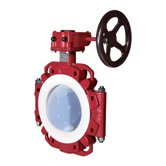
Series NKS-N, NKSP-N
Shut-off and Control Butterfly Valve
metal-coated
Keep for future use!
This operating manual must be strictly observed before
transport, installation, operation and maintenance
Subject to change without notice.
Reproduction is generally permitted with indication of the source.
© Richter Chemie-Technik GmbH.
9520-021-en Revision 18 Edition 05/2022
Advertisement
Table of Contents

Related Manuals for Richter NKS-N Series


Summary of Contents for Richter NKS-N Series
- Page 1 Keep for future use! This operating manual must be strictly observed before transport, installation, operation and maintenance Subject to change without notice. Reproduction is generally permitted with indication of the source. © Richter Chemie-Technik GmbH. 9520-021-en Revision 18 Edition 05/2022...
-
Page 2: Table Of Contents
Series NKS-N, NKSP-N Page 2 List of Contents 6 Installation .......... 11 List of Contents ........2 6.1 Direction of flow and installation position ... 11 Relevant documents ......... 2 6.2 Installation ..........11 1 Technical data ........3 6.2.1 Additional advice for shut-off and control butterfly valve with actuator 1.1 Type plate, CE and body markings ..... -
Page 3: Technical Data
Series NKS-N, NKSP-N Page 3 Technical data Manufacturer: Weight: See Section 1.3 Richter Chemie-Technik GmbH Dimensions and individual parts: Otto-Schott-Str. 2 See sectional drawings in Section 9. D-47906 Kempen Telephone: +49 (0) 2152 146-0 Activation: Hand lever, lockable Fax: +49 (0) 2152 146-190... -
Page 4: Tightening Torques
Series NKS-N, NKSP-N Page 4 Sign for transport securing device for actuator Pipe screws, flanges to ASME Class 150 or flanges ISO/DIN drilled to ASME Class 150 Flange Tightening screws Nominal size torque [mm] [inch] [ASME] [Nm] [in-lbs] 2“ 4 x ⅝“ 3“... -
Page 5: Dimensions
Series NKS-N, NKSP-N Page 5 Dimensions Nominal size Connection [DN] [inch] [mm] [mm] [mm] 2“ 3“ 17.5 4“ 24.5 6“ 8“ 10“ 12“ 14“ See also Section 5.2, paragraph 1 Face to face to DIN EN 558-1, series 20 (ISO 5752, series 20) Connections for worm gears and brackets as per DIN ISO 5211 The inside diameter of the mounted pipe flanges must always be greater than the dimension E in the table! -
Page 6: Pressure-Temperature Diagram
Series NKS-N, NKSP-N Page 6 Pressure-temperature diagram When used in the area of application of ASME, the low temperature of ASTM A395 is limited to -20°F (-29°C) When used in the minus temperature range, the regulations applicable in the country in question must be observed. -
Page 7: Notes On Safety
Intended use the design. Butterfly valves which are used as end valves must be Richter shut-off and control butterfly valves are sealed with a blind flange at the free connection end pressure-maintaining components in accordance with and appropriately secured against unauthorised the German Pressure Equipment Directive (DGRL) for activation. -
Page 8: Safety Notes For Applications In Potentially Explosive Areas Based On The Directive 2014/34/ Ec (Atex)
Series NKS-N, NKSP-N Page 8 Safety notes for applications in potentially explosive areas based on the Directive 2014/34/ EC (ATEX) The valves are intended for use in a potentially If the valve is not completely filled with medium, explosive area and are therefore subject to the e.g. -
Page 9: Safety Note For Valves, Certified To Clean Air Act (Ta Luft)
Series NKS-N, NKSP-N Page 9 ♦ For safe and reliable operation, it must be ♦ The valve must be grounded. ensured with regular inspection intervals that the This can be achieved in the simplest way via the unit is properly serviced and kept in a perfect pipe screws using tooth lock washers. -
Page 10: Transport Securing
Series NKS-N, NKSP-N Page 10 Transport securing Disposal Parts of the valve may be contaminated with medium which is detrimental to health and the environment and therefore cleaning is not sufficient. Risk of personal injury or damage to the environment due to the medium! ♦... -
Page 11: Installation
Series NKS-N, NKSP-N Page 11 Installation ♦ Examine valve for in-transit damage, damaged ball 6.2.1 Additional advice for shut-off and valves must not be installed. control butterfly valve with actuator ♦ Before installation the valve and the connecting pipe must be carefully cleaned to remove any dirt, For single-acting actuators a locking plate 507 has especially hard foreign matter. -
Page 12: Operation
Series NKS-N, NKSP-N Page 12 Operation ♦ Operation during cavitation leads to increased Initial commissioning wear. ♦ Non-observance Normally, the valves have been tested for leaks with pressure-temperature air or water. Prior to initial operation check cover diagram can lead to damage. screws. -
Page 13: Maintenance
Series NKS-N, NKSP-N Page 13 Maintenance ♦ All repair work is to be performed by qualified ♦ Remove the opposite body screw 914/1. personnel using the appropriate tools. ♦ Replace this screw as well with a longer disman- ♦ For the arrangement, designation and item tling screw. -
Page 14: Shut-Off Element
Series NKS-N, NKSP-N Page 14 Details to Fig. 3 and 4 Shut-off element The shut-off element assembly consists of: Disc with the integrated stem (one-piece) 221 body lining 409 flexible inlay 521 Pressure gasket 412/1, 412/2 Guide pin 229 plain bearings 300/1, 300/2, 300/3 O-rings 400/1, 400/2, 400/3, 400/4 thrust ring 405/1, 405/2 pre-tensioned by the Pressure springs 952/1, 952/2... -
Page 15: Valve Actuation
9.4.3 Remotely actuated shut-off and control butterfly valves, see QM No. 0910-08-1005, available from ITT Richter on request. Richter butterfly valves can be remotely actuated by means of pneumatic, hydraulic or electric quarter-turn actuators equipped with a connection as per ISO 5211. -
Page 16: Drawings
Series NKS-N, NKSP-N Page 16 Drawings 10.1 Legend shell Retaining plate (see drawing in Section 4.4) disc/stem unit bracket guide pin throttling plate lever assembly grounding rope 300/x plain bearing 550/x disc 312/x bearing bush flexible inlay 400/x o-ring Kopfplatte 402/1 Packing ring Coupling... -
Page 17: Sectional Drawing Nks-N With Lever Assembly Dn 50-100
Series NKS-N, NKSP-N Page 17 10.3 Sectional drawing NKS-N with lever assembly DN 50-100 9520-021-en Revision 17 TM 10477 Edition 05/2022... -
Page 18: Sectional Drawing Nks-N With Lever Assembly Dn 150-350
Series NKS-N, NKSP-N Page 18 10.4 Sectional drawing NKS-N with lever assembly DN 150-350 9520-021-en Revision 17 TM 10477 Edition 05/2022... -
Page 19: Dimensional Drawing Nks-N With Lever Assembly
Series NKS-N, NKSP-N Page 19 10.5 Dimensional drawing NKS-N with lever assembly The dimensions apply to NKS-N with lever unit, worm gear and actuator. For the connecting dimensions of the worm gear and actuator, see Sections 9.6 and 9.7. 9520-021-en Revision 17 TM 10477 Edition... -
Page 20: Connecting Dimensions Worm Gear
Series NKS-N, NKSP-N Page 20 10.6 Connecting dimensions worm gear all dimensions in mm 10.7 Connecting dimensions actuator ØS all dimensions in mm Actuator see dimensions of the manufacturer 9520-021-en Revision 17 TM 10477 Edition 05/2022... - Page 24 Waste Management Law (AbfG) and the Water Resources Act (WHG) An inspection/repair of Richter products and parts will only take place, if the attached explanation is filled out cor- rectly and completely by authorized and qualified technical personnel and is available.
- Page 25 Safety Information / Declaration of No Objection Concerning the Contamination of Richter-Pumps, -Valves and Components SCOPE AND PURPOSE Each entrepreneur (operator) carries the responsibility for the health and safety of his employees. This extends also to the personnel, who implements repairs with the operator or with the contractor.
- Page 26 for credit note Phone : Fax : End user : A. Details of Richter-product: Failure description: Classification: Article number: Serial number: B. Condition of the Richter- product: Contamination : Was it in operation ? toxic ...
- Page 27 Email: RichterCedarFalls-Info@idexcorp.com Email: RichterMumbai-Info@idexcorp.com Internet: www.richter-inc.com Internet: www.richter-ct.com © Richter Chemie-Technik GmbH 2022 Edition 11/2022 Revision 3.0 Subject to change without notice. 9520B021-en These installation and operating instructions must be kept! Richter™ = Richter Chemie-Technik GmbH; IDEX™ = IDEX Corporation...
Need help?
Do you have a question about the NKS-N Series and is the answer not in the manual?
Questions and answers