Table of Contents
Advertisement
Quick Links
INSTALLATION AND OPERATING MANUAL
Series
KNR/F, KNRP/F
KNR-D/F, KNRP-D/F
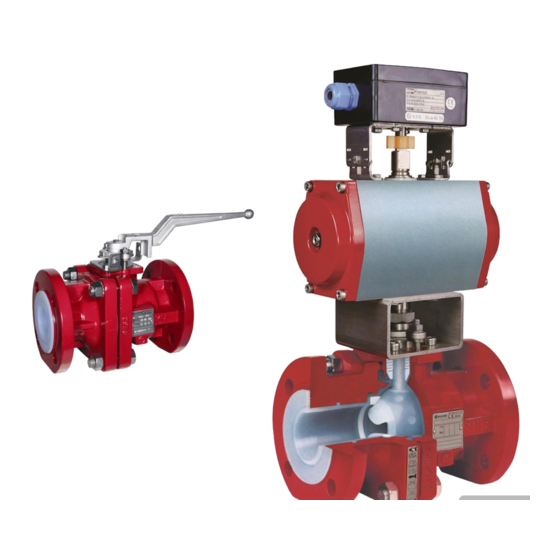
Control ball valve
with V-control ball/stem unit and Richter
ENVIPACK universal packing
Keep for future use!
This operating manual must be strictly observed before
transport, installation, operation and maintenance
Subject to change without notice.
Reproduction is generally permitted with indication of the source.
© Richter Chemie-Technik GmbH.
9520-003-en Revision 18 Edition 05/2022
Advertisement
Table of Contents

Related Manuals for Richter KNR/F Series


Summary of Contents for Richter KNR/F Series
- Page 1 INSTALLATION AND OPERATING MANUAL Series KNR/F, KNRP/F KNR-D/F, KNRP-D/F Control ball valve with V-control ball/stem unit and Richter ENVIPACK universal packing Keep for future use! This operating manual must be strictly observed before transport, installation, operation and maintenance Subject to change without notice.
-
Page 2: Table Of Contents
Series KNR/F, KNRP/F, KNR-D/F, KNRP-D/F Page 2 List of Contents List of Contents ..........2 6.3 Grounding ............9 6.4 Test pressure ........... 9 Relevant documents ......... 2 7 Operation ............9 1 Technical data ..........3 7.1 Initial commissioning ........9 1.1 Type plate, CE and body markings .... -
Page 3: Technical Data
Designation : Installation position : Control ball valve with V-control ball/stem unit and Arbitrary, a direction arrow on an additional name Richter ENVIPACK universal self-adjusting packing, plate indicates the direction of flow. See Section 1.1 two-piece body. and 10. Series: Dimensions and individual parts : →... -
Page 4: V-Control Ball/Stem Unit
Series KNR/F, KNRP/F, KNR-D/F, KNRP-D/F Page 4 Example: Additional name plate KNR, KNRP Pipe screws Flange Tightening screws nom. size torque [mm] [ISO/DIN] [Nm] Control characteristics 4 x M12 flow direction 4 x M12 Flow rate kvs and cv 4 x M12 4 x M16 4 x M16 8 x M16... -
Page 5: Actuating Torques
Series KNR/F, KNRP/F, KNR-D/F, KNRP-D/F Page 5 ∆�� Actuating torques �� �� �� − �� �� Test medium: water 20 °C = Differential pressure ratio Higher actuating torques may occur with other media. Δp = Differential pressure input/outlet Δp in bar = Absolute pressure at inlet max. -
Page 6: Pressure-Temperature Diagram
DIN EN ISO 15848-1 certificate valid from -29°C to 200 °C Notes on safety This operating manual contains fundamental Intended use information which is to be observed during installation, operation and maintenance. Richter control ball valves are pressure containing must read before installation components accordance with Pressure commissioning! -
Page 7: Improper Operation
Series KNR/F, KNRP/F, KNR-D/F, KNRP-D/F Page 7 Loads caused by earthquakes were not allowed for in Improper operation the design. Ball valves at the end of a pipe (end valve) The operational safety of the valve supplied is only must be sealed with a blind flange at the guaranteed if it is used properly in accordance with free connection end and appropriately Section 2.1... -
Page 8: Safety Note For Valves, Certified To Clean Air Act (Ta Luft)
Series KNR/F, KNRP/F, KNR-D/F, KNRP-D/F Page 8 Static discharges of non-conductive linings are reduced compared with the usual times. Actuators only produced through the interaction with a and electric peripherals, such as temperature, non-conductive medium and are therefore the pressure and flow sensors etc., must comply with responsibility of the plant operator. -
Page 9: Installation
These gaskets are available as special accessories in The V-control ball/stem unit 201 is grounded using a the Richter range. grounding spring washer 557. Test pressure The test pressure PT of a valve must not exceed the value of 1.5 x PS(PN) as per the identification of the... -
Page 10: Shutdown
Series KNR/F, KNRP/F, KNR-D/F, KNRP-D/F Page 10 Shutdown Prior to starting any repair work, the valve is to be thoroughly cleaned. Medium residue The local regulations are to be observed when dismantling the valve. may be in the valve even if it has been properly drained and flushed. -
Page 11: Maintenance
Series KNR/F, KNRP/F, KNR-D/F, KNRP-D/F Page 11 Maintenance ♦ All repair work is to be performed by qualified ♦ Remove bracket 510. ♦ Further dismantling is performed as described in personnel using the appropriate tools. ♦ For the arrangement, designation and item Section 9.1.1. -
Page 12: Conversion From Lever To Actuator
Series KNR/F, KNRP/F, KNR-D/F, KNRP-D/F Page 12 ♦ Observe the actuator position in accordance with ♦ Remove lever stop and plug. the actuator operating manual. ♦ Check the fits of the coupling , bracket ♦ Tighten setscrew 904/4 in the coupling 804. and actuator ♦... -
Page 13: Sectional Drawing Ball Valve With Lever
Series KNR/F, KNRP/F, KNR-D/F, KNRP-D/F Page 13 10.2 Sectional drawing ball valve with lever Holes of the flange- and housing screws view displaced by 45°. 9520-003-en Revision 18 TM 10477 Edition 05/2022... -
Page 14: Sectional Drawing Ball Valve With Actuator
Series KNR/F, KNRP/F, KNR-D/F, KNRP-D/F Page 14 10.3 Sectional drawing ball valve with actuator Holes of the flange- and housing screws view displaced by 45°. 9520-003-en Revision 18 TM 10477 Edition 05/2022... -
Page 15: View And Section Ball Valve With Lever
Series KNR/F, KNRP/F, KNR-D/F, KNRP-D/F Page 15 10.4 View and section ball valve with lever 10.5 Sections ball valve with actuator 9520-003-en Revision 18 TM 10477 Edition 05/2022... -
Page 16: Dimensional Drawing Ball Valve With Lever
Series KNR/F, KNRP/F, KNR-D/F, KNRP-D/F Page 16 10.6 Dimensional drawing ball valve with lever 200/150 * * DN 200 with reduced bore DN150. all dimensions in mm Flange connecting dimensions: DIN EN 1092-2, type B (ISO 7005-2, type B) PN 16 or flanges drilled to ASME 16.5 Class 150 9520-003-en Revision 18 TM 10477... -
Page 17: Dimensional Drawing Ball Valve With Gear Dn200
Series KNR/F, KNRP/F, KNR-D/F, KNRP-D/F Page 17 10.7 Dimensional drawing ball valve with gear DN200 9520-003-en Revision 18 TM 10477 Edition 05/2022... -
Page 18: Dimensional Drawing Ball Valve With Actuator
Series KNR/F, KNRP/F, KNR-D/F, KNRP-D/F Page 18 10.8 Dimensional drawing ball valve with actuator Connecting dimen. acc. to ISO 5211 60 ** 200/150 * * DN 200 with reduced bore DN 150 ** H2 = 3.15” (80mm) if F10 or F12 on the actuator side Dimensions L1, L2, L3, H3 and H4 vary depending on the actuator manufacturer. -
Page 19: Flange Connection Dimensions
Series KNR/F, KNRP/F, KNR-D/F, KNRP-D/F Page 19 10.9 Flange connection dimensions DN 200/150 with reduced bore DN 150 all dimensions in mm DIN EN 1092-2, Form B (ISO 7005-2, Form B) Flansche gebohrt nach PN 16 ASME B16.5 Class 150 ØD Øk n x d... - Page 24 Waste Management Law (AbfG) and the Water Resources Act (WHG) An inspection/repair of Richter products and parts will only take place, if the attached explanation is filled out cor- rectly and completely by authorized and qualified technical personnel and is available.
- Page 25 Safety Information / Declaration of No Objection Concerning the Contamination of Richter-Pumps, -Valves and Components SCOPE AND PURPOSE Each entrepreneur (operator) carries the responsibility for the health and safety of his employees. This extends also to the personnel, who implements repairs with the operator or with the contractor.
- Page 26 for credit note Phone : Fax : End user : A. Details of Richter-product: Failure description: Classification: Article number: Serial number: B. Condition of the Richter- product: Contamination : Was it in operation ? toxic ...
- Page 27 Email: RichterCedarFalls-Info@idexcorp.com Email: RichterMumbai-Info@idexcorp.com Internet: www.richter-inc.com Internet: www.richter-ct.com © Richter Chemie-Technik GmbH 2022 Edition 09/2022 Revision 2.0 Subject to change without notice. 9520B003-en These installation and operating instructions must be kept! Richter™ = Richter Chemie-Technik GmbH; IDEX™ = IDEX Corporation...
Need help?
Do you have a question about the KNR/F Series and is the answer not in the manual?
Questions and answers