Advertisement
Quick Links
Advertisement

Subscribe to Our Youtube Channel
Related Manuals for Lanner EAI-I130


Summary of Contents for Lanner EAI-I130
- Page 1 EAI-I130 User Manual Embedded Computing Platform Version: 1.3 Date of Release: 2022-12-29...
- Page 2 - assumed to be qualified in the servicing of computer equipment, such as professional system integrators, or service personnel and technicians. The latest version of this document can be found on Lanner’s official website, available either through the product page or through the Lanner Download Center page with a login account and password.
- Page 3 EAI-I130 User Manual Taiwan Corporate Headquarters China Lanner Electronics Inc. Beijing L&S Lancom Platform Tech. Co., Ltd. 7F, No.173, Sec.2, Datong Rd. Guodong LOFT 9 Layer No. 9 Huinan Road, Xizhi District, New Taipei City 22184, Huilongguan Town, Changping District, Beijing...
- Page 4 EAI-I130 User Manual This document is copyrighted © 2022 by Lanner Electronics Inc. All rights are reserved. The original manufacturer reserves the right to make improvements to the products described in this manual at any time without notice. No part of this manual may be reproduced, copied, translated or transmitted in any form or by any means without the prior written permission of the original manufacturer.
- Page 5 EAI-I130 User Manual Follow these guidelines to ensure general safety: Keep the chassis area clear and dust-free during and after installation. Do not wear loose clothing or jewelry that could get caught in the chassis. Fasten your tie or scarf and roll up your sleeves.
- Page 6 EAI-I130 User Manual Wear an ESD-preventive wrist strap, ensuring that it makes good skin contact. If no wrist strap is available, ground yourself by touching the metal part of the chassis. Periodically check the resistance value of the antistatic strap, which should be between 1 and 10 megohms (Mohms).
- Page 7 EAI-I130 User Manual Before turning on the device, ground the grounding cable of the equipment. Proper grounding (grounding) is very important to protect the equipment against the harmful effects of external noise and to reduce the risk of electrocution in the event of a lightning strike.
- Page 8 EAI-I130 User Manual Package Content..........................9 Ordering Information ......................... 9 System Specifications ........................10 Front Panel ............................11 Rear Panel ............................12 Block Diagram........................... 14 Internal Jumpers and Connector ...................... 15 Installing Storage Module Card (Optional) ..................25 Installing Wi-Fi Module Card (Optional) ..................26 Installing 5G Module Card (Optional) ....................
- Page 9 EAI-I130 User Manual The EAI-I130 is an industrial-grade inference box PC with NVIDIA® Jetson Xavier NX/Nano , up to 21 TOPS AI performance, 5G/Wifi6 support, IP40 standard fanless design and -40° C To 70° C operating temperature range. It also comes with 2x GigE PoE LANs, support for IEEE 802.3 af/at PoE (+), 1x HDMI, 2x USB 2.0, 2x RS232/422/485 (COM1 &...
- Page 10 EAI-I130 User Manual SKU A/B: 6-core NVIDIA Carmel ARM® v8.2, 64-bit, 6MB L2 + 4MB L3 SKU C: Quad-core ARM A57 @ 1.43GHz Processor System SKU A/B: 384-core NVIDIA Volta with 48 Tensor Cores SKU C: 128-core NVIDIA Maxwell Fanless...
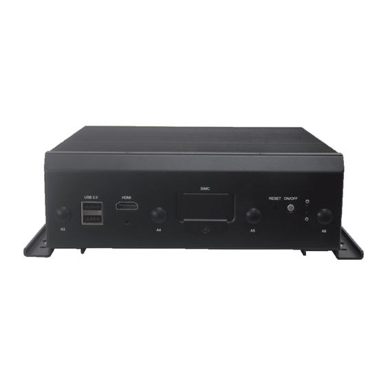
- Page 11 EAI-I130 User Manual EAI-I130A/B/C Description USB Port 2x USB 2.0 Type A Ports Display 1x HDMI Port with Screw Lock SIMC Cover SIMC Cover w/ Intrusion Design for 2x Nano SIM & 1x SD Card Reset Button 1x Reset Button...
- Page 12 EAI-I130 User Manual EAI-I130A/B Description 1x 2x5-pin Terminal Block for isolated; COM/CAN Port 2x RS232/422/485 (COM1 & COM2; COM2 is optional for 1x CAN 2.0A/B) 1x 2x6-pin Terminal Block: 4x DI (support PNP/NPN/dry contact), 4x DO (support dry/sink contact); Audio 1x Line-in;...
- Page 13 EAI-I130 User Manual EAI-I130C Description 1x 2x5-pin Terminal Block for isolated; COM Port 2x RS232/422/485 (COM1 & COM2) 1x 2x6-pin Terminal Block: 4x DI (support PNP/NPN/dry contact), 4x DO (support dry/sink contact); 1x Line-in; Audio 1x Line-out 1x 10/100/1000Mbps LAN RJ45 w/ IEEE802.3af/at PoE (+) w/ surge 2KV...
- Page 14 EAI-I130 User Manual The block diagram indicates how data flows among components on the motherboard. Please refer to the following figure for your motherboard’s layout design.
- Page 15 EAI-I130 User Manual EAI-I130A/B LAN2 JCN2 Audio1 LAN1 JPOESD1 CON1 JOPENCASE2 USB1 NGFF1 JM2B1 JOPENCASE1 LED1 JBAT1 HDMI1 USB2 PSBTN1 M2_E-KEY1 RSTBTN1...
- Page 16 EAI-I130 User Manual EAI-I130C Audio1 LAN1 JPOESD1 CON1 JOPENCASE2 USB1 NGFF1 JM2B1 JOPENCASE1 LED1 HDMI1 USB2 JBAT1 PSBTN1 RSTBTN1...
- Page 17 EAI-I130 User Manual CONN1 SIM2 SIM1 J1: Force Recovery Install Jumper for SOM upgrade. Description FORCE_RECOVERY_N USB1: Micro USB for SOM Upgrade Install J1 jumper and flash SOM via this micro USB Port Description VBUS_SENSE USB_DN USB_DP...
-
Page 18: Isp Mode
EAI-I130 User Manual SW1: MCU UART Trace Switch Latch 1 & Latch 2 turn ON, Latch 3 & Latch 4 turn OFF for Normal Operation (Default) Latch 1 & Latch 2 turn OFF, Latch 3 & Latch 4 turn ON for MCU Upgrade Program. - Page 19 EAI-I130 User Manual J13: SOM Debug UART Description UART2_PWR UART2_TXD UART2_RXD JCN2: CAN Terminal Resistor (1-2) = Enable Terminal Resistor (Default) (2-3) = Disable Terminal Resistor Description CANL CANH JPOESD1: Enable/Disable POE Function Install jumper for disable POE channel (1-2) = Disable LAN1 POE...
- Page 20 EAI-I130 User Manual JCASEOPEN2 Description JCASEOPEN1_R CONN1: Heater CONN. Description PHEAT J2: Power-up Mode (1-2) = Auto-ON (Default) (2-3) = Manual ON Description BMCU_ACOK_CN Pull down 10K to GND J4: PCIe Switch Debug Port Description PCIESW_SMCL PCIESW_SMDA PCIESW_INT_HP J5: PCIe Switch UART Port...
- Page 21 EAI-I130 User Manual JM2B1: Install Jumper Depends on Different WWAN Module (1-2) = EM9191 Function PIN, install jumper for EM9191 (Default). NC for other WWAN module. (3-4) = EM9191 Function PIN, install jumper for EM9191 (Default). NC for other WWAN module.
- Page 22 EAI-I130 User Manual NGFF1: M.2 M-Key Description Description Description PCIE_CLK_N PCIE_WAKE PCIE_RX1_N PCIE_CLK_P PCIE_RX3_N PCIE_RX1_P PCIE_RX3_P PCIE_TX1_M2_N M2_M_PEDET PCIE_TX3_M2_N PCIE_TX1_M2_P PCIE_TX3_M2_P I2C SCL PCIE_RX0_N I2C SDA PCIE_RX2_N PCIE_RX0_P ALERT_N PCIE_RX2_P PCIE_TX0_M2_N PCIE_TX2_M2_N PCIE_TX0_M2_P PCIE_RST_R PCIE_TX2_M2_P PCIE_CLK_REQ J6: M.2 B-Key Description...
- Page 23 EAI-I130 User Manual USB2_D+ RESET W_DIS1# USB2_D- WWAN_LED# M2B_P20_PCIE_DIS M2B_P22_VBUS_SENSE M2B_P26_GPS_DISABLE# USDSS_RX_N UIMH_RST1 USDSS_RX_P UIMH_CLK1 UIMH_DATA1...
- Page 24 EAI-I130 User Manual To reduce the risk of personal injury, electric shock, or damage to the unit, please remove all power connections to completely shut down the device, and wear ESD protection gloves when handling the installation steps. 1. Power off the system and disconnect the power cord.
- Page 25 EAI-I130 User Manual The system supports one M.2 M-Key module card for additional memory storage. Please follow the steps for installation. 1. Power off the system, turn the system around, and open the bottom chassis cover. 2. Locate the M.2 M-Key slot on the motherboard.
- Page 26 EAI-I130 User Manual The system supports one M.2 E-Key slot for a Wi-Fi module card, an optional accessory. Wi-Fi module requires two antennas. Please follow the steps to install the Wi-Fi module card. 1. Power off the system, turn the system around, and open the bottom chassis cover.
- Page 27 EAI-I130 User Manual This system features one M.2 B-Key slot for a 5G module card, supporting a dual SIM design. 5G module will require four antennas. Please follow the procedures for the installation of the 5G module card. 1. Power off the system, turn the system around, and open the bottom chassis cover.
-
Page 28: Front And Rear Panel
EAI-I130 User Manual Installing 5G Antennas Front & Rear Panel ㄉ ㄉ Locate the four (4) antenna RF cables. ㄉ Locate the four (4) IPEX connectors on the 5G module card. 2. Connect the RF cables to the 5G module card. - Page 29 EAI-I130 User Manual The SIM slot on the front panel supports 2x Nano SIM cards. The SIM socket supports the push-push mechanism, allowing inserting and ejecting the SIM card to be as easy as one push. 1. Locate the SIM card cover on the front panel.
- Page 30 EAI-I130 User Manual The system can be mounted on a flat surfaced wall. Please take the following into considerations when mounting the system onto the wall. 1. Fix the wallmount brackets onto the system bottom by securing them with six provided screws.
- Page 31 EAI-I130 User Manual Align the four mounting holes on the system’s brackets with the four anchoring bolts you just installed on the wall. Drive four (4) long screws into the anchoring bolts to secure the system.
- Page 32 EAI-I130 User Manual Host Environment (Reference): Ubuntu 18.04.4 LTS CrossCompiler : gcc-linaro-7.3.1-2018.05-x86_64_aarch64-linux-gnu.tar.xz Download L4T 32.7.1 from this link. Deploy L4T # ls jetson_linux_r32.7.2_aarch64.tbz2 public_sources.tbz2 tegra_linux_sample-root-filesystem_r32.7.2_aarch64.tbz2 # tar -xf jetson_linux_r32.7.2_aarch64.tbz2 # tar -xf public_sources.tbz2 # cd Linux_for_Tegra/rootfs/ # sudo tar xpf ../../tegra_linux_sample-root-filesystem_r32.7.2_aarch64.tbz2 # cd ..
- Page 33 INSTALL_MOD_PATH=<L4T Path>/Linux_for_Tegra/rootfs/ Program SOM’s Image. 8.1 short EAI-I130’s J1 for ForceRecoveryMode 8.2 Prepare a USB Cable (Micro-USB to USB Type A) Insert USB Cable (Micro-USB Side) to your EAI-I130, then Plug USB Cable (Type A Side) to your Host USB1 (Micro-USB)
- Page 34 EAI-I130 User Manual 8.3 Power-on EAI-I130 8.4 You should see a nVIDIA Device with lsusb at Host 8.5 Type this command for program SOM # ./flash.sh jetson-xavier-nx-devkit-emmc mmcblk0p1...
- Page 35 EAI-I130 User Manual 0. Host Environment (Reference): Ubuntu 18.04.4 LTS Cross Compiler: gcc-linaro-7.3.1-2018.05-x86_64_aarch64-linux-gnu.tar.xz 1. Download L4T 32.7.1 from this link. Deploy L4T # ls jetson-210_linux_r32.7.2_aarch64.tbz2 public_sources.tbz2 tegra_linux_sample-root-filesystem_r32.7.2_aarch64.tbz2 # tar -xf jetson-210_linux_r32.7.2_aarch64.tbz2 # tar -xf public_sources.tbz2 # cd Linux_for_Tegra/rootfs/ # sudo tar xpf ../../tegra_linux_sample-root-filesystem_r32.7.2_aarch64.tbz2 # cd ..
- Page 36 INSTALL_MOD_PATH=<L4T Path>/Linux_for_Tegra/rootfs/ Program SOM’s Image. 8.1 short EAI-I130’s J1 for ForceRecoveryMode 8.2 Prepare a USB Cable (Micro-USB to USB Type A) Insert USB Cable (Micro-USB Side) to your EAI-I130, then Plug USB Cable (Type A Side) to your Host USB1 (Micro-USB)
- Page 37 EAI-I130 User Manual 8.3 Power-on EAI-I130 8.4 You should see a nVIDIA Device with lsusb at Host 8.5 Type this command for program SOM # ./flash.sh jetson-nano-devkit-emmc mmcblk0p1...
- Page 38 EAI-I130 User Manual RJ-45 LAN LED 10/100/1G Amber Green Speed Amber (Active) Green (Link) Blinking / Data access 100M Blinking / Data access Blinking / Data access 1. When cable is plug-in and network is linked. Both LED will be bright. The behavior is as defined.
- Page 39 EAI-I130 User Manual 1. All products are under warranty against defects in materials and workmanship for a period of one year from the date of purchase. 2. The buyer will bear the return freight charges for goods returned for repair within the warranty period;...
- Page 40 EAI-I130 User Manual When requesting RMA service, please fill out the following form. Without this form enclosed, your RMA cannot be processed.
Need help?
Do you have a question about the EAI-I130 and is the answer not in the manual?
Questions and answers