
Subscribe to Our Youtube Channel
Related Manuals for Lanner EAI-I500


Summary of Contents for Lanner EAI-I500
- Page 1 Embedded Computing Platform Hardware Platforms for Intelligent Edge Computing EAI-I500 User Manual Version: 1.0 Date of Release: 2024-05-31...
- Page 2 - assumed to be qualified in the servicing of computer equipment, such as professional system integrators, or service personnel and technicians. The latest version of this document can be found on Lanner’s official website, available either through the product page or through the Lanner Download Center page with a login account and password.
- Page 3 EAI-I500 User Manual Contact Information Taiwan Corporate Headquarters China Lanner Electronics Inc. Beijing L&S Lancom Platform Tech. Co., Ltd. 7F, No.173, Sec.2, Datong Rd. Guodong LOFT 9 Layer No. 9 Huinan Road, Xizhi District, New Taipei City 22184, Huilongguan Town, Changping District, Beijing...
- Page 4 EAI-I500 User Manual Acknowledgment Intel® and Intel® Core are trademarks of Intel Corporation or its subsidiaries in the U.S. and/or other countries. Microsoft Windows and MS-DOS are registered trademarks of Microsoft Corp. All other product names or trademarks are properties of their respective owners.
- Page 5 EAI-I500 User Manual Safety Guidelines Follow these guidelines to ensure general safety: Keep the chassis area clear and dust-free during and after installation. Do not wear loose clothing or jewelry that could get caught in the chassis. Fasten your tie or scarf and roll up your sleeves.
- Page 6 The installation of this product must be performed by trained specialists; otherwise, a non-specialist might create the risk of the system’s falling to the ground or other damages. Lanner Electronics Inc. shall not be held liable for any losses resulting from insufficient strength for supporting the system or use of inappropriate installation components.
- Page 7 EAI-I500 User Manual Warning This equipment must be grounded. The power cord for product should be connected to a socket-outlet with Class I Equipment. This equipment must be earthed. The power plug must be connected to a properly wired earth ground socket outlet.
-
Page 8: Table Of Contents
EAI-I500 User Manual Table of Contents Chapter 1: Product Overview .............. 10 Package Content..........................10 Additional Accessories ........................10 Ordering Information ........................11 Specifications............................ 11 Front Panel ............................13 Rear Panel ............................14 Motherboard Information........................ 15 Internal Jumpers and Connector ...................... 16 Chapter 2: Hardware Setup .............. - Page 9 EAI-I500 User Manual Boot Menu ............................76 Save and Exit Menu .......................... 77 Appendix A: LED Indicator Explanations ........... 79 Appendix B: Enable 2.5GbE LAN Functionality ........80 Appendix C: Terms and Conditions ............ 81 Warranty Policy ..........................81...
-
Page 10: Chapter 1: Product Overview
EAI-I500 User Manual CHAPTER 1: PRODUCT OVERVIEW Lanner’s EAI-I500 stands as a state-of-the-art inference box meticulously crafted for retail applications. It harnesses the formidable capabilities of the Intel® Meteor Lake H/U CPU. This forward-looking solution provides a robust and efficient platform meticulously designed to address the distinctive requirements of the retail sector. -
Page 11: Ordering Information
EAI-I500 User Manual Ordering Information SKU No. Description Intel® Core Ultra 7 processor 165H (Meteor Lake-H), 2x DDR5 5600 non-ECC SODIMM, 4x Ethernet Ports (1x OOB Optional), 2x COM Ports, 2x 2.5” SATA Drive EAI-I500A Bays, 4x USB Ports, 2x DP 1.2 Port, 4x DI & 4x DO, 1x M.2 B-Key (NVMe) PCIe Gen3*4 Slot, 1x M.2 E-Key for Wi-Fi 6/6E, 1x M.2 B-Key for LTE/5G... - Page 12 EAI-I500 User Manual LED Indicators Power/Status LED Indicator, refer to Appendix A 1x DP 1.2 Port Display Port 3x 2.5GbE Rj45; 1x GbE RJ45 (OOB Optional) Ethernet Port 1x Mic-In; 1x Line-Out Audio Ports 6x Antenna Holes for Wi-Fi/LTE/5G Modules Antenna 1x M.2 2280 M-Key PCIe Gen3*4 (NVMe);...
-
Page 13: Front Panel
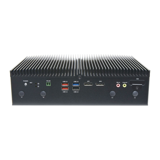
EAI-I500 User Manual Front Panel Description Power Button 1x ON/OFF Power Button Reset Button 1x Reset Button LED Indicators Storage/Power Status LED Indicators Power Switch 1x 2-Pin Terminal Block Remote Power Switch USB Port 2x USB 3.2, 1x USB 3.0, 1x 2.0 Type A Port Display Port 2x DP 1.2 Ports... -
Page 14: Rear Panel
EAI-I500 User Manual Rear Panel Description Power Input 1x 2-Pin Terminal Block for +24Vdc Power Input Ground Hole 1x Semi-shearing hole for grounding 3x 2.5GbE RJ45 Ports; LAN Port 1x GbE RJ45 (Optional OOB Port) COM Port 2x DB9, RS-232/422/485 COM Ports (1x Optional for OOB Console) -
Page 15: Motherboard Information
EAI-I500 User Manual Motherboard Information Block Diagram The block diagram indicates how data flows among components on the motherboard. -
Page 16: Internal Jumpers And Connector
EAI-I500 User Manual Internal Jumpers and Connector The pin headers on the motherboard are often associated with important functions. With the shunt (Jumper) pushed down on the designated pins (the pin numbers are printed on the circuit board, surrounding the pin header), certain feature can be enabled or disable. - Page 17 EAI-I500 User Manual Normal Program 1-8, 2-7 3-6, 4-5 Signal 1 ON (Default) SOUT3 2 ON (Default) SIN3 3 OFF MCU_UART_RX_ISP 4 OFF MCU_UART_TX_ISP J2 (OOB_POWER) 1-2: Default Signal +P3V3_STBY +P3V3_USB_OOB USB1 (OOB_FW) Signal +P5V_VBUS USB0_DM USB0_DP JSPI1 Signal SOC_SPI_IO3_ROM...
- Page 18 EAI-I500 User Manual ESPI1 Signal ESPI_CLK ESPI_IO1 ESPI_RST# ESPI_IO0 ESPI_CS0# +P3V3 ESPI_IO3 ESPI_IO2 +P3V3_STBY COM1-2 Signal DCD# DTR# RTS# CTS# MIC1 Signal GND_AUD MIC_OUT_L MIC1_JD GND_AUD MIC_OUT_R...
- Page 19 EAI-I500 User Manual LINE1 Signal GND_AUD FRONT_OUT_L FRONT_JD GND_AUD FRONT_OUT_R M2_E_KEY1 (M.2 Slots E-Key) Signal Signal Signal +P3V3 PERST#EKEY USB2_P10 +P3V3 +P3V3 PMC_I2C_SCL USB2_N10 PCH_WAKE# LED_WLAN1- GSPI0_CS0# CNV_RGI_DT I2S2_SCLK CNV_WR_D1_DN CNV_UART0_CTS# CNVI_WT_D1N CNV_RF_RESET# PCH_PCIE_TXP9 CNV_WR_D1_DP PCH_GPP_F0 CNVI_WT_D1P I2S2_RXD PCH_PCIE_TXN9 CL_RST#...
- Page 20 EAI-I500 User Manual M2_B_KEY1: M.2 Slots B-Key Signal Signal Signal M2_1_Config_3 V3P3_G1/NC V3P3_G1 E3_CLKREQ- UIM1_VPP_1 CLK_PCIE_N_MPCIE2_SW V3P3_G1 USB3_M2_R1- E3_WAKE- UIM1_RST CLK_PCIE_P_MPCIE2_SW PWROFF1# USB3_M2_R1+ USB2_2+ UIM1_CLK W_DIS1# USB2_2- UIM1_DAT ANTCTL0 NGFF_LED_1N USB3_M2_T1- UIM1_PWR ANTCTL1 USB3_M2_T1+ V3P3_G1/NC ANTCTL2 M2_1_UIM2_Detect ANTCTL3 PCH_PCIE_RXN5 M2_1_UIM1_DET...
- Page 21 EAI-I500 User Manual GEN4_LED PCIE4_TX_N1 PCIE4_TX_N3 +P3V3 PCIE4_TX_N1 PCIE4_TX_P3 +P3V3 +P3V3 PCIE4_RX_N0 PCIE4_RX_N2 +P3V3 PCIE4_RX_P0 SUSCLK PCIE4_RX_P2 +P3V3 +P3V3 PCIE4_TX_N0 +P3V3 PCIE4_TX_N2 PCIE4_TX_P0 +P3V3 PCIE4_TX_P2 PLTRST_GEN4 CN1 (DIO) Signal Signal DO_2 DI_2 DO_4 DO_1 DI_4 DI_1 DO_3 DI_3 +PDIO_COM SATA 1-2...
- Page 22 EAI-I500 User Manual JPW 2-3 Signal +P12V +P5V DP 1-2 Signal Signal LANE0+ LANE0- LANE1+ LANE1- LANE2+ LANE2- LANE3+ LANE3- AUX CH+ AUX CH- HOT PLUG RETURN DP PWR USB2: USB 2.0 + 3.0 Description Description +P5V_S_USB2_2 USB2_N1 USB2_P1 Description...
- Page 23 EAI-I500 User Manual LAN1: 2X4 Dual RJ45 with LED Description 2.5G/1G/100M A1/B1 LAN1_MDX0N/ LAN2_MDX0N A2/B2 LAN1_MDX0P/ LAN2_MDX0P A3/B3 LAN1_MDX1N/ LAN2_MDX1N A4/B4 LAN1_MDX1P/ LAN2_MDX1P A5/B5 LAN1_MDX2N/ LAN2_MDX2N A6/B6 LAN1_MDX2P/ LAN2_MDX2P A7/B7 LAN1_MDX3N/ LAN2_MDX3N A8/B8 LAN1_MDX3P/ LAN2_MDX3P A9/B9 LAN1_T/ LAN2_T A10/B10 GND/ GND...
- Page 24 EAI-I500 User Manual PCIE1: X8 PCIE Slot Description Description PRSNT1# SMCLK JTAG2 SMDAT JTAG3 JTAG4 3.3V JTAG5 JTAG1 3.3V 3.3VAUX 3.3V WAKE# PERST# KEY B RSVD REFCLKA+ HSOP0 REFCLKA- HSON0 HSIP0 PRSNT2# HSIN0 HSOP1 RSVD HSON1 HSIP1 HSIN1 HSOP2 HSON2...
- Page 25 EAI-I500 User Manual HSIP4 HSIN4 HSOP5 HSON5 HSIP5 HSIN5 HSOP6 HSON6 HSIP6 HSIN6 HSOP7 HSON7 HSIP7 PRSNT2# HSIN7 J3: MIPI-GSML/FPDIII Signal Signal +P3V3 I2C0_SCL I2C0_SDA CSI_F_DP_1- CSI_F_DN_1 CSI_F_DP_0 CSI_F_DN_0 CSI_E_DP_0 CSI_E_DN_0 CSI_E_DP_1 CSI_E_DN_1 CSI_E_CLK_P CSI_E_CLK_N...
-
Page 26: Chapter 2: Hardware Setup
EAI-I500 User Manual CHAPTER 2: HARDWARE SETUP To reduce the risk of personal injury, electric shock, or damage to the unit, please remove all power connections to completely shut down the device and wear ESD protection gloves when handling the installation steps. -
Page 27: Installing System Memory (Optional)
EAI-I500 User Manual Installing System Memory (Optional) The motherboard supports two system memory slots, please follow the steps for installation. 1. Power off the system, turn the system around, and open the bottom chassis cover. Metal Cover A 2. Locate the DIMM socket area on the motherboard. -
Page 28: Installing Nvme Storage Card (Optional)
EAI-I500 User Manual Installing NVMe Storage Card (Optional) The system supports one M.2 M-Key for NVMe storage module expansion. Please follow the steps for installation. 1. Power off the system, turn the system around, and open the bottom chassis cover. -
Page 29: Installing Wi-Fi Module (Optional)
EAI-I500 User Manual Installing Wi-Fi Module (Optional) The system supports one M.2 E-key slot for a Wi-Fi module card, which requires two antennas. Please follow these steps to install the Wi-Fi module. 1. Power off the system, turn the system around, and open the bottom chassis cover. - Page 30 EAI-I500 User Manual Installing Wi-Fi Antennas Front Panel 1. Locate the two (2) antenna hole placement (A2, A3). Locate the two (2) IPEX connectors on the Wi-Fi module. 2. Connect RF cables to the IPEX connectors on the Wi-Fi module and screw the other end of the cables in the antenna holes.
-
Page 31: Installing Lte/5G Module (Optional)
EAI-I500 User Manual Installing LTE/5G Module (Optional) The motherboard provides one M.2 B-Key slot for an LTE or 5G module card. The LTE module requires two antennas, while the 5G module requires four antennas. Please follow these steps to install the LTE/5G module. - Page 32 EAI-I500 User Manual Installing LTE Antennas Front Panel 1. Locate the two (2) antenna hole placement (A1, A4). Locate the two (2) IPEX connectors on the LTE module card. 2. Connect the RF cables to the IPEX connectors on the LTE module and screw the other end of the cables in the antenna holes.
- Page 33 EAI-I500 User Manual Installing 5G Antennas Front Panel Rear Panel 1. Locate the four (4) antenna hole placement (A1, A4, A5, A6). Locate the four (4) IPEX connectors on the 5G module card. 2. Connect the RF cables to the IPEX connectors on the 5G module and screw the other end of the cables in the antenna holes.
- Page 34 EAI-I500 User Manual 3. Then, screw on the four (4) antennas on the front and rear panel of the system.
-
Page 35: Installing Sim Cards
EAI-I500 User Manual Installing SIM Cards The SIM slot on the side panel supports one Nano SIM card. The SIM socket supports the push-push mechanism, allowing inserting and ejecting the SIM card to be as easy as one push. 1. Locate the SIM card cover on the front panel. -
Page 36: Installing Disk Drive (Optional)
EAI-I500 User Manual Installing Disk Drive (Optional) The system supports two 2.5” HDD/SSD drive for additional data storage. Please follow the steps for installation. An HDD/SSD Kit includes: 1x or 2x 2.5” SSD 1x or 2x SATA Cables 2.5” SSD SATA Cables 1. - Page 37 EAI-I500 User Manual 4. Insert the other end of the SATA data cable to the SATA1 port and SATAPWR1 port on the motherboard. 5. Repeat steps to install another SSD Storage.
-
Page 38: Wall Mounting
EAI-I500 User Manual Wall Mounting The system can be mounted on a flat surfaced wall. Please take the following into considerations when mounting the system onto the wall. Note: All pictures shown are for illustration purposes only, actual product may vary due to specific model or enhancement. - Page 39 EAI-I500 User Manual 4. Align the four mounting holes on the system’s brackets with the four anchoring bolts you just installed on the wall. 5. Drive four long screws into the anchoring bolts to secure the system.
-
Page 40: Chapter 3: Software Setup
EAI-I500 User Manual CHAPTER 3: SOFTWARE SETUP BIOS Setup The system has AMI BIOS built-in, with a SETUP utility that allows users to configure required settings or to activate certain system features. Pressing the <Tab> or <Del> key immediately allows you to enter the Setup utility. -
Page 41: Main Page
EAI-I500 User Manual Main Page Setup main page contains BIOS information and project version information. Feature Description BIOS Vendor: American Megatrends Core Version: AMI Kernel version, CRB code base, X64 Compliancy: UEFI version, PI version BIOS Information Project Version: BIOS release version... -
Page 42: Advanced Page
EAI-I500 User Manual Advanced Page Select the Advanced menu item from the BIOS setup screen to enter the “Advanced” setup screen. Users can select any of the items in the left frame of the screen. - Page 43 EAI-I500 User Manual CPU Configuration Feature Options Description Intel (VMX) Disabled When enabled, a VMM can utilize the additional hardware Virtualization Enabled capabilities provided by Vanderpool Technology. Technology Disabled Enable/Disable the AVX and AVX2 Instructions Enabled Disabled Hyper-Threading Enable or Disable Hyper-Threading Technology.
- Page 44 EAI-I500 User Manual Enables Txt Alias Checking capability. Changes require full Txt Disabled capability before it will take effect. It is a one-time only change; Alias Check Request Enabled next reboot will be reset. DPR Memory Size Reserve DPR memory size (0-255) MB...
- Page 45 EAI-I500 User Manual Efficient-Core Information Performance-Core Information...
- Page 46 EAI-I500 User Manual Power & Performance...
- Page 47 EAI-I500 User Manual CPU – Power Management Control Feature Options Description Boot Max Disabled Enable/Disable Boot Maximum Frequency in CPU Frequency Enabled strap Max Battery Boot performance Select the performance state that the BIOS will set Max Non-Turbo Performance mode starting from reset vector.
- Page 48 EAI-I500 User Manual GT/Media-Power Management Control Feature Options Description Enabled Check to enable render standby support. (Render Standby) Disabled Enabled Check to enable Media standby support. (Media Standby) Disabled Maximum GT frequency limited by the user. Choose between 2400MHz (RPN) and 6900MHz (RP0).
- Page 49 EAI-I500 User Manual System Agent (SA) Configuration Feature Options Description Above 4GB MMIO Enabled Enable/Disable above 4GB MemoryMappedIO BIOS assignment. BIOS assignment Disabled This is enabled automatically when Aperture Size is set to 2048MB.
- Page 50 EAI-I500 User Manual Memory Configuration Feature Options Description Memory Test on Disabled Enable Or Disable Base Memory Test Run on Warm Boot Warm Boot Enabled Dynamic 3.5 GB 3.25 GB 3 GB 2.75 GB Maximum Value of TOLUD. Dynamic assignment would 2.5 GB...
- Page 51 EAI-I500 User Manual VMD Configuration Feature Options Description Enable VMD Enabled Enable/Disable to VMD controller controller Disabled...
- Page 52 EAI-I500 User Manual VT-d Configuration Feature Options Description Check to enable VT-d function on MCH. This option will VT-d Enabled be grayed out when 'X2APIC Enable' option is configured as 'Enabled'. Pre-boot DMA Enabled Enable DMA Protection in Pre-boot environment.
- Page 53 EAI-I500 User Manual CVF Support...
- Page 54 EAI-I500 User Manual PCIE Configuration Feature Options Description PCI Express Root Enabled Control the PCI Express Root Port. Port PXPxx Disabled...
- Page 55 EAI-I500 User Manual PCH-IO Configuration Feature Options Description Power On Restore AC Specify what state to go to when power is re-applied Power Off Power Loss after a power failure (G3 state). Last State...
- Page 56 EAI-I500 User Manual SATA Configuration Feature Options Description Enabled SATA Controllers(s) Enable/Disable SATA Device Disabled...
- Page 57 EAI-I500 User Manual PCH-IO Configuration...
- Page 58 EAI-I500 User Manual Firmware Update Configuration Feature Options Description Me FW Image Disabled Enable/Disable Me FW Image Re-Flash function. This Re-Flash Enabled control item will return to “disabled” at next boot.
- Page 59 EAI-I500 User Manual Trusted Computing Feature Options Description Enables or disables BIOS support for security device. By Security Device Enabled disabling this function, OS will not show Security Device. Support Disabled TCG EFI protocol and INT1A interface will not be available.
- Page 60 EAI-I500 User Manual Control PXE Boot Feature Options Description Disabled LAN1 Control PXE Boot LAN2 Control PXE Boot from Onboard LAN# LAN3 LAN4...
- Page 61 EAI-I500 User Manual F81804 Super IO Configuration...
- Page 62 EAI-I500 User Manual Serial Port 1 Configuration Feature Options Description Disabled Serial Port Enable or Disable Serial Port (COM) Enabled Device Settings IO=3F8h; IRQ=4...
- Page 63 EAI-I500 User Manual Serial Port 2 Configuration Feature Options Description Disabled Serial Port Enable or Disable Serial Port (COM) Enabled Device Settings IO=2F8h; IRQ=3;...
- Page 64 EAI-I500 User Manual COM Mode Configuration Feature Options Description RS232 RS422 COM1 Mode Select COM mode RS232/422/485 RS485 Disabled COM1 Termination Enable/Disabled COM termination Enabled RS232 COM2 Mode RS422 Select COM mode RS232/422/485 RS485 Disabled COM2 Termination Enable/Disabled COM termination...
- Page 65 EAI-I500 User Manual Hardware Monitor Feature Description SYS1 Temp This value reports the System temperature SYS2 Temp This value reports the System temperature (Close to CPU) This value reports the CPU VCORE Input voltage CPU VCORE VBAT This value reports the VBAT Input voltage 3.3V...
- Page 66 EAI-I500 User Manual Serial Port Console Redirection Feature Options Description Console Disabled Console Redirection Enable or Disable. Redirection Enabled...
- Page 67 EAI-I500 User Manual Console Redirection Settings Feature Options Description Emulation: VT100 ANSI: Extended ASCII char set. VT100+ VT100: ASCII char set. Terminal Type VT-UTF8 VT100+: Extends VT100 to support color, function keys, etc. ANSI VT-UTF8: Uses UTF8 encoding to map Unicode chars onto 1 or more bytes.
- Page 68 EAI-I500 User Manual Disabled With this mode enabled only text will be sent. This is to capture Recorder Mode Terminal data. Enabled Resolution Disabled Enables or disables extended terminal resolution. 100x31 Enabled VT100 LINUX XTERMR6 Putty KeyPad Select FunctionKey and KeyPad on Putty.
- Page 69 EAI-I500 User Manual PCI Subsystem Settings Feature Options Description Disabled Disables 64bit capable Device Resources to be Allocated in Above 4G Decoding Above 4G Address Space. Enabled Disabled If system has SR-IOV capable PCIe Devices, this option Enables SR-IOV Support Enabled or Disables Single Root IO Virtualization Support.
- Page 70 EAI-I500 User Manual USB Configuration Feature Options Description Enabled This is a workaround for OSes without XHCI hand-off support. The XHCI Hand-off Disabled XHCI ownership change should be claimed by XHCI driver. USB Mass Storage Disabled Enable/Disable USB Mass Storage Driver Support.
- Page 71 EAI-I500 User Manual Network Stack Configuration Feature Options Description Disabled Network Stack Enable/Disable UEFI Network Stack Enabled Disabled Enable/Disable IPv4 PXE boot support. If IPv4 PXE Support Enabled disabled, IPv4 PXE boot support will not be available. Disabled Enable/Disable IPv4 HTTP boot support. If...
- Page 72 EAI-I500 User Manual NVMe Configuration...
-
Page 73: Security Page
EAI-I500 User Manual Security Page Select the Security item from the BIOs setup screen to enter the Security page. Users can select any of the items in the left frame of the screen. Feature Description Setup Administrator If ONLY the Administrator's password is set, it only limits access to Setup and is only asked for when entering Setup. - Page 74 EAI-I500 User Manual Secure Boot Feature Options Description Secure Boot feature is Active if Secure Boot is Enabled, Platform Disabled Secure Boot Key (PK) is enrolled and the System is in User mode. The mode Enabled change requires platform reset Secure Boot mode options: Standard or Custom.
- Page 75 EAI-I500 User Manual Key Management Feature Options Description Factory Key Disabled Install factory default Secure Boot keys after the platform reset Provision Enabled and while the System is in Setup mode Force System to User Mode. Install factory default Secure Boot...
-
Page 76: Boot Menu
EAI-I500 User Manual Boot Menu Select the Boot menu item from the BIOS setup screen to enter the “Boot” setup screen. Users can select any of the items in the left frame of the screen. Feature Options Description The number of seconds to wait for setup activation key. -
Page 77: Save And Exit Menu
EAI-I500 User Manual Save and Exit Menu Select the Save and Exit menu item from the BIOS setup screen to enter the “Save and Exit” setup screen. Users can select any of the items in the left frame of the screen. - Page 78 IIOT-I531 User Manual ■ Restore Defaults Restore default values for all setup options. Select “Yes” to load Optimized defaults. Note: The items under Boot Override may not be the same as image above, as it would depend on the actual devices connected on the system.
-
Page 79: Appendix A: Led Indicator Explanations
IIOT-I531 User Manual APPENDIX A: LED INDICATOR EXPLANATIONS RJ45 LAN LED 2.5Gb RJ45 LAN LED Define: Speed Green (Link/Active) Green/Amber (Speed) 100M ON / Blinking (Data Access) ON / Blinking (Data Access) ON (Amber) 2.5G ON / Blinking (Data access) ON (Green) 1. -
Page 80: Appendix B: Enable 2.5Gbe Lan Functionality
IIOT-I531 User Manual APPENDIX B: ENABLE 2.5GBE LAN FUNCTIONALITY The EAI-I500 comes equipped with Intel® i226 Ethernet Controller. In order to enable Intel® i226 2.5GbE LAN functionality, your Linux Kernel should be version 5.16.18. or higher. The OS Support matrix can be found here. -
Page 81: Appendix C: Terms And Conditions
IIOT-I531 User Manual APPENDIX C: TERMS AND CONDITIONS Warranty Policy 1. All products are under warranty against defects in materials and workmanship for a period of one year from the date of purchase. 2. The buyer will bear the return freight charges for goods returned for repair within the warranty period; whereas the manufacturer will bear the after-service freight charges for goods returned to the user. - Page 82 IIOT-I531 User Manual RMA Service Request Form When requesting RMA service, please fill out the following form. Without this form enclosed, your RMA cannot be processed.
Need help?
Do you have a question about the EAI-I500 and is the answer not in the manual?
Questions and answers