
Subscribe to Our Youtube Channel
Related Manuals for Lanner ECA-5540


Summary of Contents for Lanner ECA-5540
- Page 1 ECA-5540 User Manual Edge Computing Appliance Platform Hardware Platforms for Edge Computing ECA-5540 User Manual Version: 1.0 Date of Release:2024-01-29...
- Page 2 - assumed to be qualified in the servicing of computer equipment, such as professional system integrators, or service personnel and technicians. The latest version of this document can be found on Lanner’s official website, available either through the product page or through the Lanner Download Center page with a login account and password.
- Page 3 ECA-5540 User Manual Contact Information Taiwan Corporate Headquarters China Lanner Electronics Inc. Beijing L&S Lancom Platform Tech. Co., Ltd. 7F, No.173, Sec.2, Datong Rd. Guodong LOFT 9 Layer No. 9 Huinan Road, Xizhi District, New Taipei City 22184, Huilongguan Town, Changping District, Beijing...
- Page 4 ECA-5540 User Manual Copyright and Trademarks This document is copyrighted © 2024. All rights are reserved. The original manufacturer reserves the right to make improvements to the products described in this manual at any time without notice. No part of this manual may be reproduced, copied, translated or transmitted in any form or by any means without the prior written permission of the original manufacturer.
- Page 5 ECA-5540 User Manual Safety Guidelines Follow these guidelines to ensure general safety: Keep the chassis area clear and dust-free during and after installation. Do not wear loose clothing or jewelry that could get caught in the chassis. Fasten your tie or scarf and roll up your sleeves.
- Page 6 The installation of this product must be performed by trained specialists; otherwise, a non-specialist might create the risk of the system’s falling to the ground or other damages. Lanner Electronics Inc. shall not be held liable for any losses resulting from insufficient strength for supporting the system or use of inappropriate installation components.
- Page 7 ECA-5540 User Manual temperature (Tma) specified by the manufacturer. Reduced Air Flow - Installation of the equipment in a rack should be such that the amount of airflow required for safe operation of the equipment is not compromised. Mechanical Loading - Mounting of the equipment in the rack should be such that a hazardous condition is not achieved due to uneven mechanical loading.
- Page 8 ECA-5540 User Manual Electrical Safety Instructions Before turning on the device, ground the grounding cable of the equipment. Proper grounding (grounding) is very important to protect the equipment against the harmful effects of external noise and to reduce the risk of electrocution in the event of a lightning strike. To uninstall the equipment, disconnect the ground wire after turning off the power.
-
Page 9: Table Of Contents
ECA-5540 User Manual Table of Contents Chapter 1: Product Overview ............11 Main Features ..........................11 Package Content ......................... 11 Ordering Information ......................... 11 Optional Accessories ........................11 System Specifications ......................... 12 Front Panel ..........................13 Rear Panel ..........................13 Chapter 2: Motherboard information .......... - Page 10 ECA-5540 User Manual Chapter 4: BIOS Setup ..............46 Main Page ........................... 47 Advanced Page ........................... 48 Platform Configuration ....................... 64 Socket Configuration ........................69 Server Mgmt ..........................94 Security ............................99 Boot Menu ..........................102 Save & Exit Menu ........................103 Appendix A: LED Indicator Explanations ........
-
Page 11: Chapter 1: Product Overview
ECA-5540 User Manual CHAPTER 1: PRODUCT OVERVIEW Lanner's ECA-5540 offers a scalable, high-performance platform for telecom operators to build and deploy 5G radio access networks that are open, efficient, and secure. The appliance is specifically designed for distributed/centralized RAN deployments and enables operators to enable multi-access edge computing and services with ease. -
Page 12: System Specifications
ECA-5540 User Manual System Specifications Form Factor 1U 19” Rackmount 5th Gen Intel® Xeon® Scalable Processors Processor Options (Codenamed Emerald Rapids) CPU Socket Platform 1x LGA 4677 socket type Chipset Emmisburg PCH Security Acceleration Intel® QuickAssist Technology (By CPU SKU) -
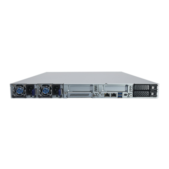
Page 13: Front Panel
ECA-5540 User Manual Front Panel Description Power Supply AC 1+1 Redundant Power Supply PCIe Expansion 2x PCIe LP Slots OCP NIC 1x OCP 3.0 NIC Slot Reset Button 1x Reset Button LED Indicators Power / Status LED Indicators Power Button... -
Page 14: Chapter 2: Motherboard Information
ECA-5540 User Manual CHAPTER 2: MOTHERBOARD INFORMATION Block Diagram Intel Emerald Rapids... - Page 15 ECA-5540 User Manual Motherboard Layout The motherboard layout shows the connectors and jumpers on the board. Refer to the following picture as a reference of the pin assignments and the internal connectors.
-
Page 16: Internal Jumpers And Connectors
Description PWM control RPM sense RPM sense +12V 2. JOPEN1: Case Open Indication Pin # Description FP_CHASSIS_INTRUSION 3. JSPITPM: For Lanner TPM Module (IAC-TPM04) or SPI Fixture Debug Purpose Pin # Description Pin # Description SPI_HOLD# SPI_CS1# SPI_CS0# SPI_3V3 SPI_MISO... - Page 17 4. J5: For System or BMC Console Debug Purpose Pin # Description 5. JPMBUS1: For Lanner Power Debug Purpose Pin # Description SMB_PMBUS_STBY_LVC3_R_SDA SMB_PMBUS_STBY_LVC3_R_SCL 6. JESPI80PORT: For Lanner eSPI Fixture Debug Purpose Pin # Description Pin # Description ESPI_CLK ESPI_IO1 ESPI_RST#...
- Page 18 ECA-5540 User Manual 11. J13: For Boot Up BIOS Selection Pin # Description First BIOS Second BIOS 12. JGPP_D6: For Flash Descriptor Security Override Pin # Description Normal Override 13. JMERCVR1: For ME Force Update Pin # Description Normal ME Force Update 14.
- Page 19 ECA-5540 User Manual +P12V +P12V +P12V +P12V +P12V SMB_SCL SMB_CDA PERST PRSNTA_N +P3V3 PRSNTB_N REFCLK+ REFCLK- CPUPETN7 CPUPERN7 CPUPETP7 CPUPERP7 CPUPETN6 CPUPERN6 CPUPETP6 CPUPERP6 CPUPETN5 CPUPERN5 CPUPETP5 CPUPERP5 CPUPETN4 CPUPERN4 CPUPETP4 CPUPERP4 CPUPETN3 CPUPERN3 CPUPETP3 CPUPERP3 CPUPETN2 CPUPERN2 CPUPETP2 CPUPERP2...
- Page 20 ECA-5540 User Manual 17. J4: OCP X16 Slot Pin # Description Pin # Description WAKE# +P3V3_AUX OB10 OA10...
- Page 21 ECA-5540 User Manual OB11 OA11 +P3V3 OB12 OA12 +P3V3 OB13 OA13 OB14 OA14 +P12V +P12V +P12V +P12V +P12V +P12V SMB_SCL SMB_CDA PERST PRSNTA_N +P3V3 PRSNTB_N REFCLK+ REFCLK- CPUPETN0 CPUPERN0 CPUPETP0 CPUPERP0 CPUPETN1 CPUPERN1 CPUPETP1 CPUPERP1 CPUPETN2 CPUPERN2 CPUPETP2 CPUPERP2 CPUPETN3...
- Page 22 ECA-5540 User Manual CPUPETN7 CPUPERN7 CPUPETP7 CPUPERP7 PRSNTB PRSNTB CPUPETN8 CPUPERN8 CPUPETP8 CPUPERP8 CPUPETN9 CPUPERN9 CPUPETP9 CPUPERP9 CPUPETN10 CPUPERN10 CPUPETP10 CPUPERP10 CPUPETN11 CPUPERN11 CPUPETP11 CPUPERP11 CPUPETN12 CPUPERN12 CPUPETP12 CPUPERP12 CPUPETN13 CPUPERN13 CPUPETP13 CPUPERP13 CPUPETN14 CPUPERN14 CPUPETP14 CPUPERP14 CPUPETN15 CPUPERN15 CPUPETP15...
- Page 23 ECA-5540 User Manual CPUPETP2 CPUPERP3 CPUPETN2 CPUPERN3 CPUPETP3 CPUPERP0 CPUPETN3 CPUPERN0 CPUPETP0 CPUPERP0 CPUPETN0 CPUPERN0 CPUPETP0 CPUPERP1 CPUPETN0 CPUPERN1 CPUPETP1 CPUPERP2 CPUPETN1 CPUPERN2 CPUPETP2 CPUPERP3 CPUPETN2 CPUPERN3 CPUPETP3 REFCLK+ CPUPETN3 REFCLK- PWR_ON_N SMB_SCL PWR_ON_N SMB_CDA PWRFL_N WAKE# PWRFL_N PRSNTB_N PRSNTB_N...
- Page 24 ECA-5540 User Manual CPUPETN1 CPUPERN2 CPUPETP2 CPUPERP3 CPUPETN2 CPUPERN3 CPUPETP3 CPUPERP0 CPUPETN3 CPUPERN0 CPUPETP0 CPUPERP0 CPUPETN0 CPUPERN0 CPUPETP0 CPUPERP1 CPUPETN0 CPUPERN1 CPUPETP1 CPUPERP2 CPUPETN1 CPUPERN2 CPUPETP2 CPUPERP3 CPUPETN2 CPUPERN3 CPUPETP3 REFCLK+ CPUPETN3 REFCLK- SMB_SCL SMB_CDA WAKE# +P3V3_AUX PERST_N +P3V3_AUX 20. CONN3: SATA Connector...
- Page 25 ECA-5540 User Manual SATA_P1_RXN SATA_P0_RXN SATA_P3_RXP SATA_P2_RXP SATA_P3_RXN SATA_P2_RXN SATA_P1_TXP SATA_P0_TXP SATA_P1_TXN SATA_P0_TXN SATA_P3_TXP SATA_P2_TXP SATA_P3_TXN SATA_P2_TXN 21. J6: X8 Slot (EIO-55401) Pin # Description Pin # Description +12V +P5V_DSW +12V +12V +P5V_AUX +12V +P5V_AUX +12V +P5V_AUX +12V +P5V_AUX +12V...
- Page 26 ECA-5540 User Manual USB3_P5_TXN USB3_P4_RXP USB3_P4_RXN USB3_P5_RXP LAN1_LINK_100_N USB3_P5_RXN LAN1_LINK_1000_N LAN1_MDI0P RST_PLTRST_N LAN1_MDI0N FM_PCH_PWRBTN_N FP_RESET_N RST_BMC_RSTBTN_OUT_N LAN1_MDI1P FP_CPLD_RST_BTN_N LAN1_MDI1N FP_PWR_BTN_N FP_PWR_BTN_NCT_N FM_BMC_PFR_PWRBTN_OUT_N LAN1_MDI2P FM_BMC_PWRBTN_OUT_N LAN1_MDI2N FP_BMC_PWR_BTN_R2_N RST_CPLD_RSTBTN_OUT_R_N FP_BMC_RST_BTN_N LAN1_MDI3P RST_BMC_RSTBTN_OUT_R_N LAN1_MDI3N FP_BMC_PWR_BTN_R_N PCH_GRN_GPPC_A_19 LAN1_LINK_ACT_N PCH_YLW_GPPC_A_18 22. JATX2: GPU Power CONN...
-
Page 27: Chapter 2: Hardware Setup
ECA-5540 User Manual CHAPTER 2: HARDWARE SETUP To minimize the risk of personal injury, electric shock, or system damage, ensure all power connections are disconnected to fully shut down the device. Additionally, wear ESD protection gloves while carrying out the procedures in this chapter. -
Page 28: Installing The System Memory
ECA-5540 User Manual Installing the System Memory The motherboard supports 16 memory slots for DDR5 registered DIMM. Supported System Memory Summary Total Slots Supported DIMM Capacity 8GB, 16GB, 32GB, 64GB Memory Size Maximum 1024GB RDIMM (64GB*16) Memory Type DDR5 ECC RDIMM 4000MHZ Minimum DIMM Installed At least 1 memory module to boot and run from. -
Page 29: Installing M.2 Storage Modules (Optional)
ECA-5540 User Manual Installing M.2 Storage Modules (Optional) This system supports one M.2 2280 and one M.2 2242 storage module slot. Please proceed with the following steps for installation. 1. Power down the system and open the chassis. 2. Locate the M.2 module slot on the motherboard. -
Page 30: Installing Low-Profile Pcie Expansion Card (Optional)
ECA-5540 User Manual Installing Low-Profile PCIe Expansion Card (Optional) ECA-5540 comes with two Low-Profile PCIe expansion slot (Optional) for graphics card, ethernet or accelerator card. Please proceed with the following steps for installation. 1. Power off the system and open the chassis cover. - Page 31 ECA-5540 User Manual 5. Install the bracket back onto the motherboard. Secure with three (3) screws. Repeat steps if installing a second module card.
-
Page 32: Installing Gpu Graphic Card (Optional)
ECA-5540 User Manual Installing GPU Graphic Card (Optional) The ECA-5540 is equipped with a PCIe x16 FH/FL slot, suitable for GPU graphics or acceleration card expansion. Please proceed with the following steps for installation. 1. Power off the system and open the chassis cover. -
Page 33: Installing The Disk Drives (Optional)
ECA-5540 User Manual Installing the Disk Drives (Optional) This system supports two 2.5” SATA SSD drive bays. Please follow the instructions to install the disk drives. 1. Power off the system. Locate the 2.5” disk bay on the front panel. - Page 34 ECA-5540 User Manual 5. Place the mounted disk tray back into the system. Gently slide the tray in until it is securely seated, then press the tab lever until it clicks, indicating it is locked in place.
-
Page 35: Replacing The Power Supply Units
ECA-5540 User Manual Replacing the Power Supply Units Power supply units may wear down eventually. Please be noted that ECA-5540 series supports 1600W AC PSUs. Please prepare the power supply units that matching this capacity. 1. Power off the system. Locate the power supply units on the front panel. -
Page 36: Chapter 3: Remote Server Management
ECA-5540 User Manual CHAPTER 3: REMOTE SERVER MANAGEMENT Overview This document specifies the BMC firmware features. The BMC firmware implements IPMI 2.0 based on ASPEED service processor. It performs all the BMC management tasks defined by IPMI 2.0. In addition, BMC firmware runs an embedded web-server for full configuration using Web UI, which has a low learning curve. -
Page 37: Bmc Firmware Functional Description
ECA-5540 User Manual BMC Firmware Functional Description System health monitoring The BMC implements system sensor monitoring feature. It could monitor voltage, temperature, and current of critical components. System Power Management The BMC implements chassis power and resets functions for system administrators to control and manage the system power behavior. - Page 38 ECA-5540 User Manual User Management The BMC supports 9 IDs for IPMI user accounts. The maximum length of the username and password are 16 and 20 respectively, and the possible privilege levels are Callback, User, Operator, and Administrator. Moreover, the account creator can enable/disable the user account at any time. If not specified, the default...
-
Page 39: Ipmi Commands Support List
ECA-5540 User Manual IPMI Commands Support List COMMANDS NETFN IPM Device “Global” Commands Get Device ID APP (06h) Cold Reset APP (06h) Warm Reset APP (06h) Get Device GUID APP (06h) BMC Watchdog Timer Commands Reset Watchdog Timer APP (06h) - Page 40 ECA-5540 User Manual Get SEL Time UTC Offset Storage (0Ah) Set SEL Time UTC Offset Storage (0Ah) LAN Device Commands Set LAN Configuration Parameters Transport (0Ch) Get LAN Configuration Parameters Transport (0Ch) Serial/Modem Device Commands Set User Callback Options Transport (0Ch)
-
Page 41: Using Bmc Web Ui
ECA-5540 User Manual Using BMC Web UI In the address bar of your Internet browser, input the IP address of the remote server to access the BMC interface of that server. Initial access of BMC prompts you to enter username and password. A screenshot of the login screen is given... - Page 42 ECA-5540 User Manual Default User Name and Password Username: admin Password: admin The default username and password are in lower-case characters. When you log in using the default username and password, you will get full administrative rights, and it will ask you to change the default password once you log in.
- Page 43 ECA-5540 User Manual Wizard Welcome Page Introduction After the first-time login, you will see first time wizard welcome page as the following picture. Please press the “Next” button and configure your BMC step by step. On the “IPv4”, “IPv6” and “DNS” pages, you could specify the hostname and network settings of BMC.
- Page 44 ECA-5540 User Manual Web UI Layout Introduction The BMC Web UI consists of various menu items: Menu Bar A screenshot of the menu bar is shown below: Menu Bar Quick Button and Logged-in User The user information and quick buttons are located at the top right of the Web UI.
- Page 45 ECA-5540 User Manual The logged-in user information shows the logged-in user’s username, privilege, with the quick buttons allowing you to perform the following functions: Refresh: Click the icon to reload the current page. Sign out: Click the icon to log out of the Web UI.
-
Page 46: Chapter 4: Bios Setup
ECA-5540 User Manual CHAPTER 4: BIOS SETUP BIOS is a firmware embedded on an exclusive chip on the system’s motherboard. Lanner's BIOS firmware offering including market-proven technologies such as Secure Boot and Intel Boot Guard technology deliver solid commitments for the shield protection against malware, uncertified sequences and other named cyber threats. -
Page 47: Main Page
ECA-5540 User Manual Main Page Setup main page contains BIOS information and project version information. Feature Description BIOS Vendor: American Megatrends Core Version :AMI Kernel version, CRB code base, X64 BIOS Compliancy : UEFI version, PI version Information BIOS Version : BIOS release version... -
Page 48: Advanced Page
ECA-5540 User Manual Advanced Page Select the Advanced menu item from the BIOS setup screen to enter the “Advanced” setup screen. Users can select any of the items in the left frame of the screen. - Page 49 ECA-5540 User Manual Trusted Computing Feature Options Description Enables or disables BIOS support for security device. By Security Device Enabled disabling this function, OS will not show Security Support Disabled Device. TCG EFI protocol and INT1A interface will not be available.
- Page 50 ECA-5540 User Manual Trusted Computing (TPM1.2) Feature Options Description Enables or disables BIOS support for security device. By disabling Security Device Enabled this function, OS will not show Security Device. TCG EFI protocol Support Disabled and INT1A interface will not be available.
- Page 51 ECA-5540 User Manual Trusted Computing (TPM2.0) Feature Options Description Enables or disables BIOS support for security device. By Security Device Enabled disabling this function, OS will not show Security Device. TCG Support Disabled EFI protocol and INT1A interface will not be available.
- Page 52 ECA-5540 User Manual Enabled SHA256 PCR Bank Enables or disables SHA256 PCR Bank. Disabled Schedules an Operation for the Security Device. Pending None NOTE: Your computer will reboot during restart in order to operation TPM Clear change State of Security Device.
- Page 53 ECA-5540 User Manual AST2600 Super IO Configuration...
- Page 54 ECA-5540 User Manual Serial Port 1 Configuration Feature Options Description Enabled Serial Port Enable or Disable Serial Port (COM) Disabled Device Settings IO=3F8h; IRQ = 4...
- Page 55 ECA-5540 User Manual Serial Port 2 Configuration Feature Options Description Enabled Serial Port Enables or disables Serial Port 2 Disabled Device Settings IO=2F8h; IRQ = 3...
- Page 56 ECA-5540 User Manual Serial Port Console Redirection Feature Options Description COM0 Enabled Enables or disables Console Redirection Console Redirection Disabled...
- Page 57 ECA-5540 User Manual Console Redirection Settings Feature Options Description VT100: ASCII char set VT100 VT100+:Extends VT100 to support color, function VT100+ keys, etc. Terminal Type VT-UTF8 VT-UTF8:Uses UTF8 encoding to map Unicode chars onto 1 or more bytes ANSI ANSI: Extended ASCII char set 9600 Selects serial port transmission speed.
- Page 58 ECA-5540 User Manual None Flow Control can prevent data loss from buffer Hardware Flow Control overflow. RTS/CTS VT-UTF8 Combo Key Disabled Enables VT-UTF8 Combination Key Support for Enabled Support ANSI/VT100 terminals Disabled With this mode enabled, only text will be sent. This is...
- Page 59 ECA-5540 User Manual PCI Subsystem Settings Feature Options Description Enables or disables 64bit capable Devices to be Above 4G Disabled Decoded in Above 4G Address Space (Only if System Decoding Enabled Supports 64 bit PCI Decoding) If the system has SR-IOV capable PCIe Devices, this...
- Page 60 ECA-5540 User Manual USB Configuration Feature Options Description Enables Legacy USB support. Enabled Auto option disables legacy support if no USB devices are Legacy USB Disabled connected; Support Auto Disabledoption will keep USB devices available only for EFI applications. Enabled This is a workaround for OSes without XHCI hand-off support.
- Page 61 ECA-5540 User Manual Network Stack Configuration...
- Page 62 ECA-5540 User Manual NVMe Configuration...
- Page 63 ECA-5540 User Manual Control PXE Boot Feature Options Description Control Legacy PXE Disabled Select On Board LAN# Boot Boot from Enabled...
-
Page 64: Platform Configuration
ECA-5540 User Manual Platform Configuration Select the Platform menu item from the BIOS setup screen to enter the Platform Setup screen. Users can select any of the items in the left frame of the screen. Feature Options Description Displays and provides option to change the PCH... - Page 65 ECA-5540 User Manual PCH Configuration Feature Options Description SATA And RST Configuration...
- Page 66 ECA-5540 User Manual Controller 1 SATA and RST Configuration Feature Options Description Disabled SATA Configuration Enables or disables SATA Controller Enabled SATA Mode Selection AHCI Determines how SATA controller(s) operate. Disabled Port0 Enable or Disable SATA Port Enabled Disabled Hot Plug Designates this port as Hot Pluggable.
- Page 67 ECA-5540 User Manual Disabled Port2 Enable or Disable SATA Port Enabled Disabled Hot Plug Designates this port as Hot Pluggable. Enabled Disabled Configured as eSATA Configures port as External SATA (eSATA) Enabled If enabled for any of ports Staggerred Spin Up will be...
- Page 68 ECA-5540 User Manual Server ME Configuration...
-
Page 69: Socket Configuration
ECA-5540 User Manual Socket Configuration Select the Socket menu item from the BIOS setup screen to enter the Socket Setup screen. Users can select any of the items in the left frame of the screen. Feature Options Description Processor None... - Page 70 ECA-5540 User Manual Processor Configuration Feature Options Description ALL LPs Enables Logical processor (Software Method Enable LP Single LP Enable/Disable Logical Processor threads) Disabled Machine Check Enable or Disable the Machine Check Enabled...
- Page 71 ECA-5540 User Manual Hardware Disabled = MLC Streamer Prefetcher (MSR 1A4h Bit [0]) Prefetcher Enabled Adjacent Cache Disabled = MLC Spatial Prefetcher (MSR 1A4h Bit [1]) Prefetcher Enabled Disabled Extended APIC Enables or disables extended APIC support Enabled Disabled Enable Intel® TXT...
- Page 72 ECA-5540 User Manual Per-Socket Configuration Feature Options Description CPU Socket0 Configuration None None...
- Page 73 ECA-5540 User Manual CPU Socket0 Configuration Feature Options Description 0: Enable all cores. FFFFFFFFFFF: Disable all cores least one Core Disable core per CPU must be enabled. Disabling all cores is an Bitmap(Hex) invalid configuration.
- Page 74 ECA-5540 User Manual Memory Configuration Feature Options Description Auto 3200 3600 Memory 4000 Maximum Memory Frequency Selections in Mhz. Do not select Frequency 4400 Reserved. 4800 5200 5600 Memory None Displays memory topology with Dimm population information Topology...
- Page 75 ECA-5540 User Manual IIO Configuration Feature Options Description Socket0 None None Configuration Socket1 None None Configuration Intel® VT for Press <Enter> to bring up the Intel? VT for Directed I/O None Directed I/O (VT-d) (VT-d) Configuration menu. PCI-E ASPM Disable...
- Page 76 ECA-5540 User Manual Socket0 Configuration Feature Options Description Selects PCIe Subsystem Mode for selected slot(s) Gen5 Port 1 Gen4: Gen4 controller only Protocol Auto Subsystem Mode Gen5: Gen5 with or without mix mode Negotiation Auto: Auto select Selects PCIe Subsystem Mode for selected slot(s)
- Page 77 ECA-5540 User Manual Port 1A Feature Options Description In auto mode the BIOS will remove the EXP port if there is Auto PCI-E Port no device or errors on that device and the device is not HP capable. Enable/Disable is used Auto Gen 1 (2.5 GT/s)
- Page 78 ECA-5540 User Manual Port 1C Feature Options Description In auto mode the BIOS will remove the EXP port if there Auto PCI-E Port is no device or errors on that device and the device is not HP capable. Enable/Disable is used Auto Gen 1 (2.5 GT/s)
- Page 79 ECA-5540 User Manual Port 1E Feature Options Description In auto mode the BIOS will remove the EXP port if there Auto PCI-E Port is no device or errors on that device and the device is not HP capable. Enable/Disable is used Auto Gen 1 (2.5 GT/s)
- Page 80 ECA-5540 User Manual Port 2A Feature Options Description In auto mode the BIOS will remove the EXP port if there Auto PCI-E Port is no device or errors on that device and the device is not HP capable. Enable/Disable is used Auto Gen 1 (2.5 GT/s)
- Page 81 ECA-5540 User Manual Port 2E Feature Options Description In auto mode the BIOS will remove the EXP port if there Auto PCI-E Port is no device or errors on that device and the device is not HP capable. Enable/Disable is used Auto Gen 1 (2.5 GT/s)
- Page 82 ECA-5540 User Manual Port 3A Feature Options Description In auto mode the BIOS will remove the EXP port if there Auto PCI-E Port is no device or errors on that device and the device is not HP capable. Enable/Disable is used Auto Gen 1 (2.5 GT/s)
- Page 83 ECA-5540 User Manual Socket1 Configuration Feature Options Description Selects PCIe Subsystem Mode for selected slot(s) Gen5 Gen4: Gen4 controller only Port 1 Protocol Auto Gen5: Gen5 with or without mix mode Subsystem Mode Negotiation Auto: Auto select Selects PCIe Subsystem Mode for selected slot(s)
- Page 84 ECA-5540 User Manual Port 1A Feature Options Description In auto mode the BIOS will remove the EXP port if there Auto PCI- Port is no device or errors on that device and the device is not HP capable. Enable/Disable is used Auto Gen 1 (2.5 GT/s)
- Page 85 ECA-5540 User Manual Port 2A...
- Page 86 ECA-5540 User Manual Port 2E Feature Options Description In auto mode the BIOS will remove the EXP port if there Auto PCI- Port is no device or errors on that device and the device is not HP capable. Enable/Disable is used Auto Gen 1 (2.5 GT/s)
- Page 87 ECA-5540 User Manual Port 3A Feature Options Description In auto mode the BIOS will remove the EXP port if there Auto PCI- Port is no device or errors on that device and the device is not HP capable. Enable/Disable is used Auto Gen 1 (2.5 GT/s)
- Page 88 ECA-5540 User Manual Port 3E Feature Options Description In auto mode the BIOS will remove the EXP port if there Auto PCI- Port is no device or errors on that device and the device is not HP capable. Enable/Disable is used Auto Gen 1 (2.5 GT/s)
- Page 89 ECA-5540 User Manual Intel VT for Directed I/O (VT-d) Feature Options Description Enable/Disable Intel Virtualization Technology for Directed I/O (VT-d) by reporting the I/O device Intel VT for Directed Enable Disable assignment to VMM through DMAR ACPI Tables. To disable...
- Page 90 ECA-5540 User Manual Advanced Power Management Configuration Feature Options Description P State Control Configuration Sub Menu, include Turbo, XE CPU P State Control None and etc. CPU C State Control None CPU C State setting P State Control Configuration Sub Menu, include Turbo, XE...
- Page 91 ECA-5540 User Manual CPU P State Control Feature Options Description Disabled SpeedStep (Pstates) Enables or disables EIST (P-States) Enabled Max Performance Boot performance Select the performance state that the BIOS will set Max Efficient mode before OS hand off. Set by Intel Node Manager...
- Page 92 ECA-5540 User Manual CPU C State Control Feature Options Description Disabled CPU C1 auto demotion Autonomous Core C-State Control Enabled Disabled Enable/Disable CPU C6(ACPI C3) report to OS, Auto maps to CPU C6 report Enabled enable Auto Enhanced Halt State Disabled Core C1E auto promotion Control.
- Page 93 ECA-5540 User Manual Package C State Control Feature Options Description C0/C1 state C2 state C6 (non Retention) state Package C State limit, the state Auto maps is Package C State C6 (Retention) state program specific. No Limit Auto...
-
Page 94: Server Mgmt
ECA-5540 User Manual Server Mgmt Feature Options Description Enabled BMC Support Enable or disables interfaces to communicate with BMC. Disabled Wait For BMC response for specified time out. In PILOTII, Enabled BMC starts at the same time when BIOS starts during AC... - Page 95 ECA-5540 User Manual Enter the value Between 1 to 30 min for OS Boot Watchdog OS Wtd Timer Timer Expiration. Not available if OS Boot Watchdog Timer is Timeout disabled. Do Nothing Configure how the system should respond if the OS Boot...
- Page 96 ECA-5540 User Manual System Event Log Feature Options Description Disabled Enables or disables all features of System Event SEL Components Enabled Logging during boot. Erase SEL Yes, On next reset Choose options for erasing SEL. Yes, On every reset Do Nothing...
- Page 97 ECA-5540 User Manual BMC Network Configuration Feature Options Description Unspecified Select to configure LAN channel parameters statically Configuration Address Static or dynamically (by BIOS or BMC). The unspecified source DynamicBmcDhcp option will not modify any BMC network parameters DynamicBmcNonDhcp during BIOS phase.
- Page 98 ECA-5540 User Manual View System Event Log...
-
Page 99: Security
ECA-5540 User Manual Security Select the Security menu item from the BIOS setup screen to enter the Security Setup screen. Users can select any of the items in the left frame of the screen. Feature Description If ONLY the Administrator's password is set, it only limits access to Administrator Password Setup and is only asked for when entering Setup. - Page 100 ECA-5540 User Manual Secure Boot Feature Options Description Secure Boot is activated when Platform Key (PK) is enrolled, System Disabled Secure Boot mode is User/Deployed, and CSM function is disabled. Enabled Secure Boot mode selector: Secure Boot Standard In Custom mode, Secure Boot Variables can be configured without...
- Page 101 ECA-5540 User Manual Key Management Feature Options Description Factory Key Disabled Provision factory default keys on next re-boot only when Provision Enabled System in Setup Mode. Restore Factory Force System to User Mode. Configure NVRAM to contain None Keys OEM-defined factory default Secure Boot keys.
-
Page 102: Boot Menu
ECA-5540 User Manual Boot Menu Select the Boot menu item from the BIOS setup screen to enter the Boot Setup screen. Users can select any of the items in the left frame of the screen. Feature Options Description The Number of seconds to wait for setup activation key. -
Page 103: Save & Exit Menu
ECA-5540 User Manual Save & Exit Menu Select the Save and Exit menu item from the BIOS setup screen to enter the Save and Exit Setup screen. Users can select any of the items in the left frame of the screen. - Page 104 ECA-5540 User Manual ■ Restore Defaults Restore default values for all setup options. Select “Yes” to load Optimized defaults. Note The items under Boot Override may not have the same image as above, as it would depend on actual devices connected on system.
-
Page 105: Appendix A: Led Indicator Explanations
ECA-5540 User Manual APPENDIX A: LED INDICATOR EXPLANATIONS System Power / Status / HDD Activity Green: System Power Red/Green: System Status Amber: HDD Activity COLOR COLOR LED ACTION DESCRIPTION ON LCM ON BOARD Green Green Steady When system power on... -
Page 106: Appendix B: Dual Bios Introduction
To provide increased flexibility and usage protection, Lanner has released the 2nd Gen Dual BIOS function on Lanner appliances. With 2nd Gen Dual BIOS, both the primary BIOS and secondary BIOS can be updated and flashed using the BIOS Tool to run different versions of BIOS ROMS independently for maximum compatibility. - Page 107 Lanner Technical Support. Warning DO NOT power off or reset the system during BIOS updating process. Disclaimer Under no circumstances will Lanner accept responsibility or liability for damages of any kind whatsoever resulting or arising directly or indirectly from a BIOS update.
-
Page 108: Appendix C: Connect To Iproc Via Network
ECA-5540 User Manual APPENDIX C: CONNECT TO IPROC VIA NETWORK Step 1. X86 ethernet enp183s0f0(pci bus b7:00.0) set IP 192.168.100.X. Step 2. Use telnet tool to connect to IPROC, when connecting to system, port set 23 (default), connect to bcm CLI port set 12345. -
Page 109: Appendix D: Terms And Conditions
ECA-5540 User Manual APPENDIX D: TERMS AND CONDITIONS Warranty Policy 1. All products are under warranty against defects in materials and workmanship for a period of one year from the date of purchase. 2. The buyer will bear the return freight charges for goods returned for repair within the warranty period;... - Page 110 ECA-5540 User Manual RMA Service Request Form When requesting RMA service, please fill out the following form. Without this form enclosed, your RMA cannot be processed.
Need help?
Do you have a question about the ECA-5540 and is the answer not in the manual?
Questions and answers