Advertisement
Quick Links
Advertisement

Related Manuals for THORLABS SLS301


Summary of Contents for THORLABS SLS301
- Page 1 SLS301 Stabilized Benchtop Halogen Light Source User Guide...
- Page 2 6.2. Bulb Replacement ......................14 Chapter 7 Specifications ........................17 Chapter 8 Mechanical Drawings ......................18 Chapter 9 Certifications and Compliances ..................19 Chapter 10 Regulatory ...........................20 10.1. Waste Treatment is Your Own Responsibility ............20 10.2. Ecological Background ....................20 Chapter 11 Thorlabs Worldwide Contacts ..................21 ...
- Page 3 Stabilized Benchtop Halogen Light Source Chapter 1: Warning Symbol Definitions Chapter 1 Warning Symbol Definitions Below is a list of warning symbols you may encounter in this manual or on your device. Symbol Description Direct Current Alternating Current Both Direct and Alternating Current Earth Ground Terminal Protective Conductor Terminal Frame or Chassis Terminal...
- Page 4 Stabilized Benchtop Halogen Light Source Chapter 2: Safety Chapter 2 Safety The lamp comes with a switching power supply compatible with voltages from 100 to 240 VAC. There is no need to change the fuse when selecting your regional voltage. If the user needs to change the fuse located below the AC plug on the back of the unit, see Fuse Replacement on page 14.
- Page 5 Stabilized Benchtop Halogen Light Source Chapter 3: Product Overview Chapter 3 Product Overview 3.1. Planck's Law and Blackbody Radiation A black body is an object that absorbs all incident electromagnetic radiation (e.g. light), no light passes through or is reflected. However, despite the name, a black body will also emit electromagnetic radiation. The radiation of a black body in thermal equilibrium is described by Planck’s Law: Where is the radiated power per unit area of emitting surface per unit wavelength at temperature...
- Page 6 Optical Configuration The SLS301 is a Tungsten-Halogen lamp with a 150 W Halogen bulb. The bulb is placed inside the lamp housing, at the back focal point of the collimating lens, with the long axis of the filament parallel to the plano surface of the lens, giving a collimated output beam.
- Page 7 Stabilized Benchtop Halogen Light Source Chapter 3: Product Overview Here is the dimension information of the tungsten-halogen bulb. Bulb Specifications 13.5 mm Bulb 50 mm Dimensions 30 mm Filament Dimensions 6.5 mm x 1.3 mm x 3.3 mm Filament Turns Filament Section view Rectangular/1.33 mm x 3.3 mm Figure 3.4 Tungsten-Halogen Lamp Dimensions...
- Page 8 3.4. Output Stabilization Unlike traditional Halogen light sources, the SLS301 will not suffer either from a gradual decrease or short term fluctuation in brightness during its lifetime. SLS301 tungsten halogen light source is equipped with an internal feedback loop and therefore can ensure a constant intensity, low noise and long life span.
- Page 9 Lamp Controller Figure 4.1 Packaging of SLS301 There are 6 major pieces of foam inserts in the packaging of SLS301 as shown in Figure 4.1. Remove them carefully and take out the lamp and controller. Page 7 Rev E, September 28, 2018...
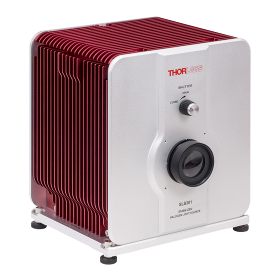
- Page 10 Stabilized Benchtop Halogen Light Source Chapter 4: Getting Started 4.3. Operation Elements Lamp Housing Front and Back Panels Figure 4.2 Front and Back Panel of SLS301 Lamp Housing L1. Shutter Control Knob L2. Collimating Lens L3. 4-40 Threaded Hole for 60mm Cage Systems ...
- Page 11 Take the lamp out of its packaging and place it onto a table top. All four feet are height adjustable to compensate any unevenness of a work surface. To adjust height, use a 4 mm hex key (one is included with the SLS301) to loose and remove the cap. Figure 4.5 Removing Cap Screws on the Adjustable Feet...
- Page 12 Stabilized Benchtop Halogen Light Source Chapter 4: Getting Started Use a 10 mm wrench (not included) to rotate the washer underneath the bottom plate. Press slightly on the plastic feet to make sure it does not rotate together with the washer. A counter clockwise rotation will increase the height. All feet are set to minimum height by default.
- Page 13 Stabilized Benchtop Halogen Light Source Chapter 4: Getting Started Connect the lamp cable to both the lamp house and controller. Please notice that there is an arrow marker on both the plug and the socket. Make sure those two makers are in line with each other, there slightly press the thread cap on to the socket, turn it clockwise to lock the connector.
- Page 14 5.3. Stabilized Operation and Monitor Output The SLS301 has a stabilized operation feature that allow it to retain constant optical output throughout the life span of the bulb. However, the output power is NOT tunable by users The “Analog out” port C1 on the pack panel of the controller provide a voltage output that is proportional to the lamp optical output power.
- Page 15 Thorlabs 60 mm cage system. And the back light port is also removable, to allow for integration to Thorlabs 30 mm cage system. Figure 5.2 shows and application idea of how to implement the SLS301 to 60 mm and 30 mm cage systems. Figure 5.2 SLS301 with 30 mm and 60 mm Cage System 5.6.
- Page 16 Stabilized Benchtop Halogen Light Source Chapter 6: Maintenance Chapter 6 Maintenance 6.1. Fuse replacement The fuse is located in the fuse drawer, C9, above the power inlet, as shown in Figure 4.4. Please use 3.15 A, 250 VAC, Type ”T”, slow blow fuse only. 6.2.
- Page 17 Stabilized Benchtop Halogen Light Source Chapter 6: Maintenance Use a 4 mm hex key or a 4 mm ball driver to remove the four cap screws on the corner of the side plate. Then remove the side plate. Figure 6.2 Remove Side Plate Loosen the two thumb screws locking the bulb by turning them counterclockwise.
- Page 18 Stabilized Benchtop Halogen Light Source Chapter 6: Maintenance Pull out the bulb by holding the flat part beneath the bulb envelope. Figure 6.4 Pull out the Bulb The bulb can be rested in the temporary bulb holder inside the lamp house as shown below. Figure 6.5 Temporary Bulb Holder To install a new bulb.
- Page 19 Stabilized Benchtop Halogen Light Source Chapter 7: Specifications Chapter 7 Specifications Specification Value 360 - 2700 nm Wavelength Range 360 - 3800 nm from Back Port Color Temperature 3400 K Color Temperature Stability ±15 K Bulb Electrical Power 150 W Filament dimensions 6.5 mm x1.3 mm x3.3 mm Output Optical power...
- Page 20 Stabilized Benchtop Halogen Light Source Chapter 8: Mechanical Drawings Chapter 8 Mechanical Drawings 213.6 mm (8.41") Remove This Plate To Access Thread Hole For 30 mm 217.0 mm Cage System (8.54") Shutter Knob 4-40 thread Hole For 60 mm Cage System (4 Places) 261.2 mm (10.28")
- Page 21 Stabilized Benchtop Halogen Light Source Chapter 9: Certifications and Compliances Chapter 9 Certifications and Compliances This device complies with Part 15 of the FCC Rules. Operation is subject to the following two conditions: (1) this device may not cause harmful interference, and (2) this device must accept any interference received, including interference that may cause undesired operation.
- Page 22 10.1. Waste Treatment is Your Own Responsibility If you do not return an “end of life” unit to Thorlabs, you must hand it to a company specialized in waste recovery. Do not dispose of the unit in a litter bin or at a public waste disposal site.
- Page 23 Stabilized Benchtop Halogen Light Source Chapter 11: Thorlabs Worldwide Contacts Chapter 11 Thorlabs Worldwide Contacts For technical support or sales inquiries, please visit us at www.thorlabs.com/contact for our most up-to- date contact information. USA, Canada, and South America UK and Ireland Thorlabs, Inc.
- Page 24 www.thorlabs.com...
Need help?
Do you have a question about the SLS301 and is the answer not in the manual?
Questions and answers