Table of Contents
Advertisement
Quick Links
Advertisement
Table of Contents
Troubleshooting

Related Manuals for THORLABS PCS-5000 Series


Summary of Contents for THORLABS PCS-5000 Series
- Page 1 PCS-5000 Series Motorized Patch-Clamp Micromanipulator User Guide...
-
Page 2: Table Of Contents
PCS-5000 Series Motorized Patch-Clamp Micromanipulator Table of Contents Chapter 1 Warning Symbols Chapter 2 Introduction 2.1. Overview 2.2. Major Components 2.2.1. PCS-520 Micromanipulator Assembly 2.2.2. PCS-503 Axis Control Unit 2.2.3. PCS-PS60 Power Supply 2.2.4. PCS-500-RP Rotation Adapter Plate Chapter 3 Description 3.1. - Page 3 PCS-5000 Series Motorized Patch-Clamp Micromanipulator 4.5.2. Left-Side Operation 4.5.3. Orthogonal Approach Axis 4.5.4. Right-Angle Bracket Adjustments 4.6. Mounting a Headstage and Pipette 4.7. Setting up the PCS-PS60 and the PCS-503 Chapter 5 Operation 5.1. Adjusting the Approach Axis Angle 5.1.1. Changing the Angle 5.1.2.
- Page 4 PCS-5000 Series Motorized Patch-Clamp Micromanipulator Chapter 7 Specifications Chapter 8 Dimensions 8.1. PCS-520 8.2. Linear Stage 8.3. Rottary Stage 8.4. Rotation Adapter Plate Chapter 9 Regulatory 9.1. Waste Treatment is Your Own Responsibility 9.2. Ecological Background Chapter 10 Warranty Chapter 11 Contacts...
-
Page 5: Chapter 1 Warning Symbols
Caution: Risk of Danger. Should this equipment be used in a manner not specified by Thorlabs, Inc., the protection provided by the equipment may be impaired. Always follow the operating instructions as indicated! IEC Class I Product: Use only the 3-prong AC power cord supplied with this equipment. -
Page 6: Chapter 2 Introduction
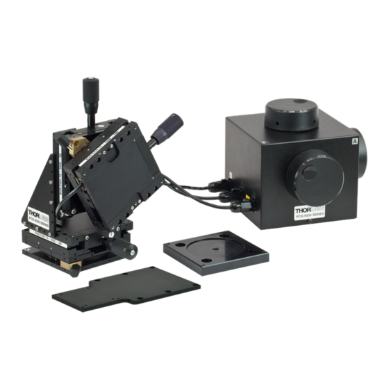
Burleigh PCS-5000 Series Motorized Patch-Clamp Micromanipulators from Thorlabs, Inc. are ultra-stable, high-resolution positioning systems designed for patch clamp recording. Thorlabs, Inc. has incorporated more than 20 years of experience and knowledge in piezoelectric actuators, precision mechanics, and electronic control to create a system that maximizes your research productivity. -
Page 7: Major Components
The power supply provides a constant low noise supply voltage for one or two PCS-503 ACU. 2.2.4. PCS-500-RP Rotation Adapter Plate The table below describes the various models of the PCS-5000 Series Motor- ized Patch-Clamp Micromanipulator. Configuration Summary of PCS-5000... - Page 8 PCS-5000 Series Motorized Patch-Clamp Micromanipulator Chapter 2: Introduction Configuration Summary of PCS-5000 Three-axis PCS-520-150/3 micromanipulator with 25 PCS-503-3 mm of manual travel. All PCS-5200 three translation stages PCS-PS60 provide 150 μm PZT fine PCS-500-RP motion. PCS-520-150/2-300/1 Three-axis micromanipulator with 25 PCS-503 mm of manual travel.
-
Page 9: Chapter 3 Description
PCS-5000 Series Motorized Patch-Clamp Micromanipulator Chapter 3: Description Chapter 3 Description 3.1. Theory of Operation The PCS-520 Micromanipulator will be mounted to your microscope. Your head- stage and pipette are mounted to the PCS-520. The manual knobs on the PCS-... - Page 10 PCS-5000 Series Motorized Patch-Clamp Micromanipulator Chapter 3: Description Figure 3–2 PCS-520 Micromanipulator Assembly The PCS-520 consists of three linear stages, two rotary pivot stages, a head- stage adapter plate, and two 90° brackets. Standardized dimensions, mounting holes, and fasteners make it easy to configure the micromanipulator for right- side, left-side, or orthogonal operation.
-
Page 11: Pcs-Ps60 Power Supply
PCS-5000 Series Motorized Patch-Clamp Micromanipulator Chapter 3: Description 3.3. PCS-PS60 Power Supply The PCS-PS60 (Figures 3-3 and 3-4) provides a regulated, very low noise con- stant voltage output for the PCS-503 ACU. This power supply can be shared by two PCS 520/PCS 503 systems when multiple manipulators are required on the same microscope. -
Page 12: Pcs-503 Axis Control Unit
PCS-5000 Series Motorized Patch-Clamp Micromanipulator Chapter 3: Description Primary Power Module This is a multi-functional assembly which integrates several functions including: the standard IEC style receptacle for attaching the line cord to the unit, the power switch, fuse holder and line voltage selector. - Page 13 PCS-5000 Series Motorized Patch-Clamp Micromanipulator Chapter 3: Description You can configure the cables to the ACU so any knob can control any stage. The adjustment knob and the cable for each of the linear stages are numbered 1, 2 and 3. The ACU knobs and the connectors on the ACU are labeled A, B and C.
-
Page 14: Chapter 4 Installation
Optional components may include: ● PCS-500 Series microscope mount ● PCS-500-PP universal post and platform mount If any components are missing, contact Thorlabs, Inc. or your local rep- resentative. Save the special carton for storage or transportation of the PCS- 5000. -
Page 15: Installing The Microscope Mount
PCS-500-15 Two-sided mount for the Nikon Diaphot 200/300 and TE 200/300 Thorlabs will continue to add to this list of microscope mounts as new micro- scopes (that are popular with patch clamp users) are introduced. If your microscope is not included, please consult Thorlabs. Other mounting solu- tions are available as special orders. -
Page 16: Gibraltar Platform Adapters (Optional)
PCS-5000 Series Motorized Patch-Clamp Micromanipulator Chapter 4: Installation Model Description PCS-500-PP11 Universal Post and Platform with Magnetic Base PCS-500-PP12 Universal Post and Platform without Magnetic Base To install the PCS-500 Series universal post and platform mount, follow the installation instructions shipped with each mount. - Page 17 PCS-5000 Series Motorized Patch-Clamp Micromanipulator Chapter 4: Installation Zeiss Axioscope FS-2 Microscope Model Description Complete platform and X-Y stage with base for Zeiss GIBRALTAR 2FS-1 Axioskop- FS-2, black plated aluminum top Complete platform and X-Y stage with base for Zeiss...
- Page 18 PCS-5000 Series Motorized Patch-Clamp Micromanipulator Chapter 4: Installation Model Description Complete platform and X-Y stage to mount to vibration GIBRALTAR EFN-2 isolation table with tapped holes for Nikon E600FN, black plated aluminum top Complete platform and X-Y stage to mount to vibration...
-
Page 19: Mounting The Pcs-520 To Your Microscope
PCS-5000 Series Motorized Patch-Clamp Micromanipulator Chapter 4: Installation 4.4. Mounting the PCS-520 to Your Microscope The PCS-500-RP Rotation Adapter Plate(Figure 4-2) allows you to position your micromanipulator at any angle. This kinematically designed adapter plate allows the PCS-520 to be mounted using one 1/4-20 screw on centerline and secured at any angle. - Page 20 PCS-5000 Series Motorized Patch-Clamp Micromanipulator Chapter 4: Installation Figure 4–3 Rotary Pivot Stage- Adjustable Stop Mechanism 4. To gain access to the clearance holes, loosen the base pivot knob and rotate the upper section of the micromanipulator assembly while keeping the lower section stationary.
-
Page 21: Configuring The Pcs-520 Micromanipulator Assembly
Figure 4–5 Mounting Hold Pattern in Linear Stage CAUTION Do not loosen or remove any of the screws holding the stage together or the stage will have to be returned to Thorlabs for reassembly. 4.5.1. Right-Side Operation When shipped, the PCS-520 Micromanipulator Assembly is normally configured for right-side operation (Figure 4-6). -
Page 22: Left-Side Operation
PCS-5000 Series Motorized Patch-Clamp Micromanipulator Chapter 4: Installation 4.5.2. Left-Side Operation To reconfigure the PCS-520 for left-side operation: 1. If the micromanipulator assembly is already mounted for right-side operation, remove the pipette and the headstage. Then remove the PCS-520 from the microscope mount. -
Page 23: Orthogonal Approach Axis
PCS-5000 Series Motorized Patch-Clamp Micromanipulator Chapter 4: Installation Figure 4–9 Reconfiguring the PCS-520 for Left-Side Operation 5. Turn the rotary pivot stage 90° to reposition the headstage pivot knob and reinstall the four screws (Figure 4-9). 6. Set the headstage to the desired angle. - Page 24 PCS-5000 Series Motorized Patch-Clamp Micromanipulator Chapter 4: Installation Figure 4–11 Removing the Headstage Adapter Plate and Approach Axis Linear Stage 3. Turn the approach axis adjustment knob to move the approach axis linear stage to the extremes of travel and gain access to the screws.
-
Page 25: Right-Angle Bracket Adjustments
PCS-5000 Series Motorized Patch-Clamp Micromanipulator Chapter 4: Installation Figure 4–13 Reconfiguring the PCS-520 for Orthogonal Operation 5. Use the four screws to attach the linear stage for the approach axis to the linear stage for the vertical axis (Figure 4-13). - Page 26 PCS-5000 Series Motorized Patch-Clamp Micromanipulator Chapter 4: Installation The pipette can be raised or lowered by moving the mounting location of the Z- axis stage up or down on the right-angle bracket. The end of the stage base can extend 30 mm (1.2") past the end of the bracket without compromising the rigid- ity.
-
Page 27: Mounting A Headstage And Pipette
PCS-5000 Series Motorized Patch-Clamp Micromanipulator Chapter 4: Installation CAUTION When making right-angle bracket adjustments, make sure the electrical cables have adequate clearance from any part of the micromanipulator assembly. Damage can result to the signal cabling if the cable restricts motion of the stage. -
Page 28: Setting Up The Pcs-Ps60 And The Pcs-503
PCS-5000 Series Motorized Patch-Clamp Micromanipulator Chapter 4: Installation Figure 4–18 Alternate Positions for Headstage Adapter Plate 4.7. Setting up the PCS-PS60 and the PCS-503 1. Place the PCS-PS60 and the PCS-503 Axis Control Unit on a firm horizontal surface. 2. Connect each linear stage of the PCS-520 Micromanipulator assembly to the PCS-503 ACU. -
Page 29: Chapter 5 Operation
PCS-5000 Series Motorized Patch-Clamp Micromanipulator Chapter 5: Operation Chapter 5 Operation 5.1. Adjusting the Approach Axis Angle The approach axis can be set to any angle. 5.1.1. Changing the Angle Using the three adjustment knobs (Figure 5-1), adjust each of the manual stages to the center of travel. -
Page 30: Setting The Adjustable Stop
PCS-5000 Series Motorized Patch-Clamp Micromanipulator Chapter 5: Operation 5.1.2. Setting the Adjustable Stop The adjustable stop mechanism on each rotary pivot stage consists of a locking ring, two set screws, a pin, and a brass block (Figure 5-2). Figure 5–2 Adjustable Stop Mechanism 1. -
Page 31: Positioning The Pipette
PCS-5000 Series Motorized Patch-Clamp Micromanipulator Chapter 5: Operation are now in the forward position and very accessible for pipette exchange. 3. After the pipette exchange, swing the pipette back under the objective as far as it will go in both the horizontal and vertical planes. The adjustable stops you set in the procedure above return the pipettes to the original home position. -
Page 32: Controlling The Pzt Position
PCS-5000 Series Motorized Patch-Clamp Micromanipulator Chapter 5: Operation CAUTION Do not force the manual adjustment knobs. A change in resistance of the coarse knob indicates the stage is at an end of travel or there is an obstruction. Readjust the stage position or clear the obstruction. -
Page 33: General Recommendation
PCS-5000 Series Motorized Patch-Clamp Micromanipulator Chapter 5: Operation 1. Locate the catch hole on the sleeve (Figure 5-5). Position the smaller head of the wrench around the sleeve, making sure the hook catches on the hole. Figure 5–5 Locating the Catch Hole 2. -
Page 34: Chapter 6 Troubleshoot
PZT actuators and cross roller bearing stages. If the system is not functioning correctly, refer to the troubleshooting guide below to identify possible causes of problems. If this guide is not successful, contact Thorlabs Customer Service or your local representative for further help. 6.1. Troubleshooting... - Page 35 PCS-5000 Series Motorized Patch-Clamp Micromanipulator Chapter 6: Troubleshoot CAUTION In the cases where the PCS-5000 is not attached directly to the microscope, it is important that the microscope itself is stable. The microscope and the mount holding the PCS-5000 must both be rigidly attached to the same base plate or optical table.
- Page 36 Check for ambient temperature changes during the experiment. For more information about minimizing thermal drift, refer to the following Application Note, available from Thorlabs, Inc.: Frederick Sachs, A Low Drift Micropipette Holder, European Journal of Physiology (1995) 429:434-435. Page 32...
-
Page 37: Fuse Holder
PCS-5000 Series Motorized Patch-Clamp Micromanipulator Chapter 6: Troubleshoot 6.2. Fuse Holder CAUTION Always replace the fuse(s) with the same type of rating: T0.3A, 250V. This fuse holder has dual-line fusing. The fuse holder can hold either 1/4" x 1/4" or 5 x 20 mm style fuses. -
Page 38: Troubleshooting The Pcs-Ps60 Power Supply
PCS-5000 Series Motorized Patch-Clamp Micromanipulator Chapter 6: Troubleshoot Figure 6–2 Position of Dual Fuse Holder Positions 4. Remove the fuses from their locations and verify the condition of both fuses. a. To replace the fuse(s), simply insert a new fuse in the same location. - Page 39 PCS-5000 Series Motorized Patch-Clamp Micromanipulator Chapter 6: Troubleshoot Figure 6–3 Location of the Shipping Clips 1. Turn the adjustment knob so that the edge of the top platen is 1/4" forward of the edge of the bottom platen (Figure 6-4).
-
Page 40: Cleaning Instructions
PCS-5000 Series Motorized Patch-Clamp Micromanipulator Chapter 6: Troubleshoot 6.4. Cleaning Instructions To clean the exterior of the axis control unit, the manipulator, or the PCS-PS60 Power Supply enclosure use only a dry or slightly dampened (with water) cloth. Be sure to unplug the supply cord prior to cleaning the unit(s). - Page 41 PCS-5000 Series Motorized Patch-Clamp Micromanipulator Chapter 7: Specifications Chapter 7 Specifications Environmental Specifications Operating Conditions Ambient Temperature 50 to 40 °C Altitude 2000 m maximum Atmospheric Pressure 70 to 106 kPa Relative Humidity 15 to 95% (non-condensing) Installation Category Pollution Degree...
- Page 42 PCS-5000 Series Motorized Patch-Clamp Micromanipulator Chapter 7: Specifications Electromagnetic Compatibility Electromagnetic Compatibility Immunity Testing- EN 61326-1:2001/A1/A2 Measurement, Control and Laboratory Equipment CE Marking: Council Directive 73/23/EEC Low Voltage Directive Counsil Directive 89/336/EEC EMC Directive FCC CLASS A Digital or Peripheral-Information to User This devices complies with Part 15 of the FCC Rules .Operation is subject to the following...
- Page 43 PCS-5000 Series Motorized Patch-Clamp Micromanipulator Chapter 7: Specifications PCS-520 Micromanipulator Assembly General AC Power 100-120 / 220 - 240 V. 0.3 A Line Frequency 50/60 Hz Fuse TO.3A 250 V Weight 2.3 lbs 5.57" x 7.00 x 2.52" Dimensions (144 mm x 178 mm x 64 mm)
- Page 44 PCS-5000 Series Motorized Patch-Clamp Micromanipulator Chapter 7: Specifications PCS-503 Axis Control Unit Number of Axes 3 Axes Contorl Type 3-Turn Potentiometer Ouput Voltage 0 to 60 V Voltage Stability Better than 0.1% (after 20 min initial warm-up period) Reolution 0.04% (1 part in 2500) Cable Length 2.9 m...
- Page 45 PCS-5000 Series Motorized Patch-Clamp Micromanipulator Chapter 8: Dimensions Chapter 8 Dimensions 8.1. PCS-520 December 28, 2019 Page 41...
- Page 46 PCS-5000 Series Motorized Patch-Clamp Micromanipulator Chapter 8: Dimensions 8.2. Linear Stage Page 42 TTN206697-D02...
- Page 47 PCS-5000 Series Motorized Patch-Clamp Micromanipulator Chapter 8: Dimensions 8.3. Rottary Stage December 28, 2019 Page 43...
- Page 48 Rotation Adapter Plate The inside set of four mounting holes on the roation plate adapter is not suited to mount the PCS-5000 Series Micromanipulator. They are used to mount a PCS-3000 Series Micromanipulator or for mounting the manipulator to a surface with tapped holes.
- Page 49 Waste Treatment is Your Own Responsibility If you do not return an “end of life” unit to Thorlabs, you must hand it to a com- pany specialized in waste recovery. Do not dispose of the unit in a litter bin or at a public waste disposal site.
- Page 50 Thorlabs, Inc. per- sonnel. The liability of Thorlabs, Inc. (except as to title) arising out of supplying of said product, or its use, whether under the foregoing warranty, a claim of negligence, or otherwise, shall not in any case exceed the cost of correcting defects in the products as herein provided.
- Page 51 PCS-5000 Series Motorized Patch-Clamp Micromanipulator Chapter 11: Contacts Chapter 11 Contacts For technical support or sales inquiries, please visit us at www.thorlabs.com/contact for our most up-to-date contact information. USA, Canada, and South America UK and Ireland Thorlabs, Inc. Thorlabs Ltd.
- Page 52 www.thorlabs.com...
Need help?
Do you have a question about the PCS-5000 Series and is the answer not in the manual?
Questions and answers