Table of Contents
Advertisement
Quick Links
Advertisement
Table of Contents

Related Manuals for THORLABS FW103 Series


Summary of Contents for THORLABS FW103 Series
- Page 1 FW103 Series Motorized Filter Wheel User Guide Original Instructions HA0179T...
-
Page 2: Table Of Contents
4.2.2 Using the APT Software ................ 10 4.2.3 Parameters ................... 11 Appendices Appendix A Specifications ................12 Appendix B Motor Pin Out Details .............. 13 Appendix C Regulatory ................14 Appendix D Thorlabs Worldwide Contacts ..........16 Page 0 16403-D01... -
Page 3: Overview
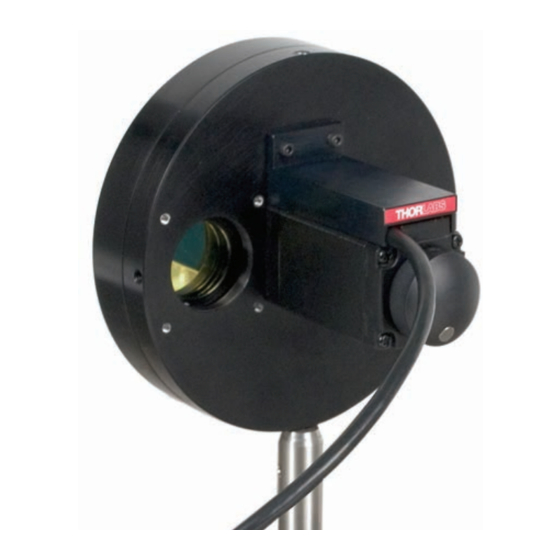
Chapter 1 Overview Chapter 1 Overview 1.1 Introduction This motorized fast-change filter wheel has been designed for applications that require sequential observations with different filters inserted in the optical path, such as multi-wavelength fluorescence imaging. Access for the fitting of filters can be gained through a removable cover without needing to unmount the filter wheel from the optomechanical setup within which it sits. -
Page 4: Chaper 2 Safety
FW103 Motorized Filter Wheel Chapter 2 Safety 2.1 Safety Information For the continuing safety of the operators of this equipment, and the protection of the equipment itself, the operator should take note of the Warnings, Cautions and Notes throughout this handbook and, where visible, on the product itself. The following safety symbols may be used throughout the handbook and on the equipment itself. -
Page 5: Chaper 3 Installation
Chapter 3 Installation Chapter 3 Installation 3.1 Unpacking. Note Retain the packing in which the unit was shipped, for use in future transportation. Caution Once removed from its packaging, the filter wheel is easily damaged by mishandling. Handle with care. 3.2 Mounting 3.2.1 General The mechanical interfacing of the wheel accepts SM1 lens tubes and 30mm cage... -
Page 6: Connecting The Motor Driver
3.3 Connecting The Motor Driver Caution It is recommended that the FW103 filter wheel is driven by either the Thorlabs KST101 K-Cube stepper motor driver or the BSC201 benchtop stepper motor controller. If the wheel is being driven by any other driver or controller, consult Section B.1. -
Page 7: Fitting The Filters
Chapter 3 Installation 3.4 Fitting the Filters Up to six Ø1.0" (25mm) filters (up to 6.35 mm thick) can be fitted onto the wheel. Thinner filters may need shorter bolts. Caution The filters can be damaged or impaired by dirt and grease. During the following procedure, handle the filters only by the housing and avoid touching the filter surface. -
Page 8: Transportation
• Thinner filters: use correspondingly shorter screws (e.g. M2 x 6 for 4 mm thickness). Note: if using filters thinner than 2.0 mm, the use of optic spacers are recommended (e.g. Thorlabs part SM1S01 or SM1S3M) to ensure secure fitting within the filter recesses. Caution Use only screws of the length specified above. -
Page 9: Chaper 4 Operation
4.1 General Caution It is recommended that the FW103 filter wheel is driven by either the Thorlabs KST101 K-Cube stepper motor driver or the BSC201 benchtop stepper motor controller. If the wheel is being driven by any other driver or controller, consult Section B.1. -
Page 10: Selecting The Stage Type
MOTOR CONTROL connector on the rear panel. 3) Ensure that the device is connected to the PC and powered up. 4) Run the Kinesis software - Start/All Programs/Thorlabs/Kinesis/Kinesis. 5) On start-up, the 'Actuator/Startup Settings' window is displayed. This window allows the correct actuator to be selected. - Page 11 Chapter 4 Operation Note To ensure correct operation, it is important to select the correct stage and axis type. If using a BSC20x series controller, select the ‘HS BSC FW103’ option. If using a KST101 controller, select the ‘HS TST FW103’ option. If using a legacy BSC0xx or BSC10x controller, or a TST001 K-Cube driver, choose the option without the ‘HS’...
-
Page 12: Using The Apt Software
1) Shut down all applications using the APT server (e.g. APT User or your own custom application). 2) Run the APT Config utility - Start/Programs/Thorlabs/APT Config/APT Config. 3) From the 'APT Configuration Utility' window, click the 'Stage' tab. 4) In the ‘Motor’ field, select the serial number of the stepper motor controller to be configured (this number can be found on the rear panel of the controller unit).. -
Page 13: Parameters
8) Click ‘Exit’ to sut down the APTConfig utility. 9) Start the APTUser utility - Start/Programs/Thorlabs/APT User/APT User. 10) The APT server reads in the stage and controller information on boot up and the settings made above are displayed in the ‘Setting’... -
Page 14: Appendix A Specifications
FW103 Motorized Filter Wheel Appendix A Specifications Parameter Value General Specifications -20°C to +40°C (Motor Specification Only) Operating Temperature BSC201 Controller: 55 to 60ms Transition Time Between Filters KST101 Driver: 250ms Motor Specifications 1.8° (50 poles & ±2 phases for 360°/200 steps) Step Angle Step Accuracy Rated Phase Current... -
Page 15: Appendix B Motor Pin Out Details
Chapter 4 Operation Appendix B Motor Pin Out Details B.1 Motor Connector Pin Out The Motor cable is terminated in a 15 way D-type connector, which provides connection to the motor controller. The pin functions are detailed in Fig. B.1. Description Description Limit Switch Ground/... -
Page 16: Appendix C Regulatory
FW103 Motorized Filter Wheel Appendix C Regulatory C.1 Declarations Of Conformity C.1.1 For Customers in Europe See Section C.2. C.1.2 For Customers In The USA This equipment has been tested and found to comply with the limits for a Class A digital device, persuant to part 15 of the FCC rules. - Page 17 FW103 Motorized Filter Wheel C.2 CE Certificate Page 15...
-
Page 18: Appendix D Thorlabs Worldwide Contacts
Waste treatment is your own responsibility. "End of life" units must be returned to Thorlabs or handed to a company specializing in waste recovery. Do not dispose of the unit in a litter bin or at a public waste disposal site. - Page 19 www.thorlabs.com...
Need help?
Do you have a question about the FW103 Series and is the answer not in the manual?
Questions and answers