Sign In
Upload
Download
Table of Contents
Contents
Add to my manuals
Delete from my manuals
Share
URL of this page:
HTML Link:
Bookmark this page
Add
Manual will be automatically added to "My Manuals"
Print this page
×
Bookmark added
×
Added to my manuals
Manuals
Brands
THORLABS Manuals
Tools
FW102C
User manual
THORLABS FW102C User Manual
Motorized filter wheel
Hide thumbs
Also See for FW102C
:
User manual
(17 pages)
1
Table Of Contents
2
3
4
5
6
7
8
9
10
11
12
13
14
15
16
17
18
19
20
21
page
of
21
Go
/
21
Contents
Table of Contents
Troubleshooting
Bookmarks
Table of Contents
Table of Contents
Chapter 1 Warning Symbol Definitions
Chapter 2 Safety
Chapter 3 Description
Features
New Design
Shipping Inventory
Chapter 4 Basic Operation
Changing and Removing the Filters
Mounting
Power
Aperture
Manual Control
External Trigger
Chapter 5 Software Control
Application Software Operation
Command Line Interface
5.2.1. Command Structure
5.2.2. Query Structure
Keywords (Commands and Queries)
Activex Control
Chapter 6 Troubleshooting and Maintenance
Removing the Filter Holder
Changing Filter Wheel Types
Error Codes & Troubleshooting
Chapter 7 Specifications
Performance
Electrical
Physical Characteristics and Interface
Pin Diagram
Chapter 8 Mechanical Drawings
Fw102C, Fw102Cneb
Fw212C, Fw212Cneb
Chapter 9 Regulatory
Chapter 10 Thorlabs Worldwide Contacts
Advertisement
Quick Links
1
Changing and Removing the Filters
2
Manual Control
3
Chapter 5 Software Control
4
Application Software Operation
5
Command Line Interface
6
Error Codes & Troubleshooting
Download this manual
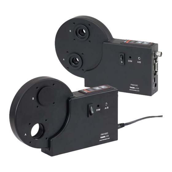
FW102C, FW102CNEB,
FW212C, FW212CNEB
Motorized Filter Wheel
User Guide
Table of
Contents
Previous
Page
Next
Page
1
2
3
4
5
Advertisement
Table of Contents
Troubleshooting
Chapter 6 Troubleshooting and Maintenance
13
Changing Filter Wheel Types
14
Need help?
Do you have a question about the FW102C and is the answer not in the manual?
Ask a question
Questions and answers
Related Manuals for THORLABS FW102C
Laboratory Equipment THORLABS FW102C User Manual
Motorized filter wheel (17 pages)
Tools THORLABS FW212C User Manual
Motorized filter wheel (21 pages)
Tools THORLABS GPXFBT-FXTA Quick Installation Manual
Fused taper handling fixtures (12 pages)
Tools THORLABS RollerBlock RB13 Series User Manual
3-axis translation stage (20 pages)
This manual is also suitable for:
Fw212c
Fw102cneb
Fw212cneb
Table of Contents
Print
Rename the bookmark
Delete bookmark?
Delete from my manuals?
Login
Sign In
OR
Sign in with Facebook
Sign in with Google
Upload manual
Upload from disk
Upload from URL


Need help?
Do you have a question about the FW102C and is the answer not in the manual?
Questions and answers