Table of Contents
Advertisement
Quick Links
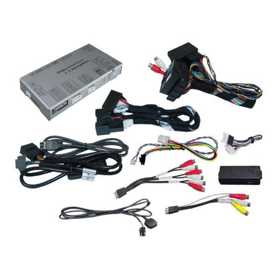
for Audi with 6,5" monitor,
Symphony or Concert radio
Video-inserter with 2 video + RGB + rear-view camera input
Product features
Video-inserter for factory-infotainment monitors
2 video-inputs for after-market devices (e.g. DVD-Player, DVB-T tuner, ...)
Built-in audio-switch (no audio-insertion)
Audio-AUX-cable for audio-insertion by factory AUX-input separately available
(item no. CAB-RCA-MQS)
Rear-view camera video-input
Automatic switching to rear-view camera input on engagement of reverse gear
RGB-input for after-market navigation
Video-in-motion (ONLY for connected video-sources)
Compatible with factory rear-view camera
AV-inputs PAL/NTSC compatible
Version 28.07.2015
v.LiNK Video-inserter
CI-VL2-CONCERT
Advertisement
Table of Contents

Related Manuals for v.link CI-VL2-CONCERT


Summary of Contents for v.link CI-VL2-CONCERT
- Page 1 Video-inserter CI-VL2-CONCERT for Audi with 6,5” monitor, Symphony or Concert radio Video-inserter with 2 video + RGB + rear-view camera input Product features Video-inserter for factory-infotainment monitors 2 video-inputs for after-market devices (e.g. DVD-Player, DVB-T tuner, …) ...
-
Page 2: Table Of Contents
Video-sources to IN1 and IN2 2.5.2. Audio-switch and audio-insertion 2.5.3. After-market rear-view camera 2.5.4. After-market navigation 2.6. Connecting video-interface and keypad 2.7. Picture settings 3. Interface operation 3.1. By MODE-button of the steering-wheel 3.2. By keypad 4. Specifications 5. Connections (video-interface) Version 28.07.2015 CI-VL2-CONCERT... -
Page 3: Prior To Installation
Technical knowledge is necessary for installation. The place of installation must be free of moisture and away from heat sources. 1.1. Delivery contents Take down the serial number of the interface and store this manual for support purposes: ____________________ Version 28.07.2015 CI-VL2-CONCERT... -
Page 4: Checking The Compatibility Of Vehicle And Accessories
1.3.2. Video signal selection after-market navigation(Dip 4) To the video interface’s RGB-input it is possible to connect a RGB- or a VGA-video source. Set dip 4 according to table. After-Market Navigation Dip 4 VGA (RGB-Input Pin 4 H-Sync, Pin 8 V-Sync) RGB NTSC Version 28.07.2015 CI-VL2-CONCERT... -
Page 5: Enabling The Interface's Video Inputs (Dip 1-3)
If power source is not taken directly from the battery, the connection has to be checked for being start-up proven and permanent. 2.1. Place of installation The interface is installed on the backside of factory monitor. Version 28.07.2015 CI-VL2-CONCERT... -
Page 6: Connection Schema
2.2. Connection schema Version 28.07.2015 CI-VL2-CONCERT... -
Page 7: Connecting Video-Interface And Can-Box
Note: Check LEDs on video-interface after reconnecting the battery, one must be on. Note: No liability for vehicle wire colours and pin definition! Possible changes by the vehicle manufacturer. The given information must be verified by the installer. Version 28.07.2015 CI-VL2-CONCERT... -
Page 8: Connection To The Factory Monitor
Before final installation of the peripheral devices, we recommend a test-run to detect incompatibility of vehicle and interface. Due to changes in the production of the vehicle manufacturer is always the possibility of incompatibility. Version 28.07.2015 CI-VL2-CONCERT... -
Page 9: Video-Sources To In1 And In2
Plug the pins of the optionally available Audio-AUX-cable CAB-RCA-MQS into the white application of the radio connector for audio insertion. Pin 1 – left audio channel Pin 2 – audio signal ground Pin 7 – right audio channel Version 28.07.2015 CI-VL2-CONCERT... - Page 10 Audio input signal R/L of source IN1 Audio output signal R/L of factory AUX or FM- modulator Ground No function Note: When switching the video interface from video-IN1 to video-IN2, the audio will also automatically be switched. Version 28.07.2015 CI-VL2-CONCERT...
-
Page 11: After-Market Rear-View Camera
6pin to 8pin cable at the black 8pin connector and connect it to the reverse gear light (+12V). For this use a relay because the reverse gear light of the vehicle is clocked (relay AC-RW1230 and AC-RS5 optional available). Note: Set Dip 5 to ON. Version 28.07.2015 CI-VL2-CONCERT... -
Page 12: After-Market Navigation
Connect the female 4pin connector of the keypad to the male 4pin connector of the video-interface. Note: We suggest to install the external push button, even if it is not going to be used by the user. Even if installed hidden, it is helpful for fault diagnosis. Version 28.07.2015 CI-VL2-CONCERT... -
Page 13: Picture Settings
Note: The white wire of the 6pin to 8pin cable can be used with a +5-12V pulse to switch the video-sources alternatively. 3.2. By keypad Alternatively or additionally to the MODE button the interface’s keypad can be used to execute interface functions. Version 28.07.2015 CI-VL2-CONCERT... -
Page 14: Specifications
Video input 0.7V~1V Video input formats PAL/NTSC RGB-video amplitude 0.7V with 75 Ohm impedance Temperature range -40°C to +85°C Weight 195g Dimensions (box only) B x H x T 182 x 24 x 100 mm 5. Connections (video-interface) Version 28.07.2015 CI-VL2-CONCERT... - Page 15 Camera is being tested under Camera input picture fluorescent light which shines Test camera under natural light outside the garage. flickers. directly into the camera. Camera input picture is Protection sticker not Remove protection sticker. bluish. removed from camera lens. Version 28.07.2015 CI-VL2-CONCERT...
- Page 16 Cut the grey wire of 6pin to 8pin and isolate both Interface switches compatibility to vehicle is ends. If problem still occurs, additionally cut the white video-sources by itself. limited. wire of 6pin to 8pin cable and isolate both ends. 10R-03 5384 Made in China Version 28.07.2015 CI-VL2-CONCERT...
Need help?
Do you have a question about the CI-VL2-CONCERT and is the answer not in the manual?
Questions and answers