Table of Contents
Advertisement
Quick Links
Compatible with Audi vehicles with
Symphony-or Concert Radio system
Video-inserter with 2 video + RGB + rear-view camera input and CAN control
Product features
Video-inserter for factory-monitors
2 video-inputs for after-market devices (e.g. DVD-Player, DVB-T tuner, ...)
Built-in audio-switch (no audio-insertion)
Rear-view camera video-input
Automatic switching to rear-view camera input on engagement of the reverse gear
Activatable parking guide lines for rear-view camera (vehicle specific restrictions
possible)
RGB-input for after-market navigation
Video-in-motion (ONLY for connected video-sources)
Compatible with factory rear-view camera
Video-inputs PAL/NTSC compatible
Version 23.02.2018
v.LiNK Video-inserter
CI-VL2-CONCERT
and 6,5" Touch-Monitor
HW:25 (V92)
CI-VL2-CONCERT
Advertisement
Table of Contents

Subscribe to Our Youtube Channel
Related Manuals for v.link CI-VL2-CONCERT


Summary of Contents for v.link CI-VL2-CONCERT
- Page 1 Video-inserter CI-VL2-CONCERT Compatible with Audi vehicles with Symphony-or Concert Radio system and 6,5” Touch-Monitor Video-inserter with 2 video + RGB + rear-view camera input and CAN control Product features Video-inserter for factory-monitors 2 video-inputs for after-market devices (e.g. DVD-Player, DVB-T tuner, …) ...
-
Page 2: Table Of Contents
2.6.4.3. Connection Video signal 2.7. Connecting video-interface and keypad 2.8. Picture settings and guide lines 3. Interface operation 3.1. By MODE-button of the steering-wheel 3.2. By keypad 4. Specifications 5. FAQ – Trouble Shooting-Interface functions Version 23.02.2018 HW:25 (V92) CI-VL2-CONCERT... -
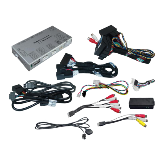
Page 3: Prior To Installation
Read the manual prior to installation. Technical knowledge is necessary for installation. The place of installation must be free of moisture and away from heat sources. 1.1. Delivery contents Take down the serial number of the interface and store this manual for support purposes: ____________________ Version 23.02.2018 HW:25 (V92) CI-VL2-CONCERT... -
Page 4: Checking The Compatibility Of Vehicle And Accessories
To delay the switch-back an additional electronic part is required. 1.3. Boxes and connectors 1.3.1. Video Interface The video-interface converts the connected after-market sources video signals into a LVDS signal which is inserted in the factory monitor using separate trigger options. Version 23.02.2018 HW:25 (V92) CI-VL2-CONCERT... -
Page 5: Can-Bus Box
Only the enabled video inputs can be accessed by switching through the interface’s video sources. It is recommended to enable only the required inputs. So the disabled inputs will be skipped while switching through the video interfaces inputs. Version 23.02.2018 HW:25 (V92) CI-VL2-CONCERT... -
Page 6: Rgb-Video Input Signal Selection For After-Market Navigation (Dip 4)
The interface needs a permanent 12V source! 2.1. Place of installation The interface is built to be installed on the backside of the factory monitor, at the climate control panel and on the backside of the vehicle’s head unit. Version 23.02.2018 HW:25 (V92) CI-VL2-CONCERT... -
Page 7: Connection Schema
2.2. Connection schema Version 23.02.2018 HW:25 (V92) CI-VL2-CONCERT... -
Page 8: Connecting Video-Interface And Can-Box
Note: Check the LEDs on the video-interface after reconnecting the battery, one must be on. Note: No liability for vehicle wire colours and pin definition! Changes by the vehicle manufacturer are possible. The given information has to be verified by the installer. Version 23.02.2018 HW:25 (V92) CI-VL2-CONCERT... - Page 9 Disconnect the female 10pin connector of the vehicle harness from the monitor’s Rear side and connect it to the male 10pin LVDS connector of the 10pin LVDS cable Connect the female 10pin connector of the 10pin LVDS cable with the male 10pin connector of the monitor Version 23.02.2018 HW:25 (V92) CI-VL2-CONCERT...
-
Page 10: Connection To The Climate Control Unit
Connect the 6pin to 8pin cable’s female 8-Pin connector to the male 8pin connector of the CAN-box. Connect the 6pin to 8pin cable’s female 6pin connector to the male 6pin connector of the video Interface. Version 23.02.2018 HW:25 (V92) CI-VL2-CONCERT... -
Page 11: After Market Rbg Navigation
Connect the female 8pin connector of the RGB cable to the male 8pin connector of the video-interface. The loose grey wires don’t have any function and have to be isolated. Connect the male 6pin connector of the RGB cable to the after-Market navigation. Version 23.02.2018 HW:25 (V92) CI-VL2-CONCERT... -
Page 12: Video-Sources To Av1 And Av2
Connect the video RCA of the AV-source 1 to the female RCA connector Video 1 of the video cable. Connect the video RCA of the AV-source 2 to the female RCA connector Video 2 of the video cable. Version 23.02.2018 HW:25 (V92) CI-VL2-CONCERT... -
Page 13: Audio-Switch And Audio-Insertion
Audio output signal R/L of factory audio AUX or FM-modulator Ground Note: If only one AV-source shall be connected, it is possible to connect the audio output of the AV-source directly to the point of audio-insertion (e.g. audio AUX input). Version 23.02.2018 HW:25 (V92) CI-VL2-CONCERT... - Page 14 Disconnect the female Quadlock connector of the vehicle harness from the Head Unit and connect it to the male connector of the Quadlock Audio cable. Connect the female Quadlock connector of the Quadlock Audio cable to the male Quadlock connector of the vehicle Head Unit. Version 23.02.2018 HW:25 (V92) CI-VL2-CONCERT...
-
Page 15: After-Market Rear-View Camera
Additionally, for the camera`s +12V Power supply the green wire of the 6pin to 8pin wire can be used. Strip a little part from the green wire of the 6pin to 8pin cable and connect it to the Power cable of the after-market rear-view camera Version 23.02.2018 HW:25 (V92) CI-VL2-CONCERT... -
Page 16: Case 2: Can-Box Does Not Receive The Reverse Gear Signal
Connect the rear-view camera power wire and the green wire (video interface side) of 6pin to 8pin cable both to output (87) of the relay. Connect permanent battery power to input (30) of relay. Version 23.02.2018 HW:25 (V92) CI-VL2-CONCERT... -
Page 17: Connecting Video-Interface And Keypad
CAM. Note: The picture settings for CAM input have to be adjusted in AV2. 2.6. Connecting video-interface and keypad Connect the female 4pin connector of the keypad to the male 4pin connector of the video-interface. Version 23.02.2018 HW:25 (V92) CI-VL2-CONCERT... -
Page 18: Picture Settings And Guide Lines
Note: If there is no communication between the CAN box and the vehicle`s CAN-bus (several vehicles aren’t compatible), the .reverse gear guide-lines can`t be shown during the vehicle’s operation, even if they once appear after having switched the system to powerless! Version 23.02.2018 HW:25 (V92) CI-VL2-CONCERT... -
Page 19: Interface Operation
0.7V with 75 Ohm impedance Temperature range -40°C to +85°C Dimensions video-box 154 x 22 x 92 mm (W x H x D) Dimensions CAN-box 73 x 22 x 30 mm (W x H x D) Version 23.02.2018 HW:25 (V92) CI-VL2-CONCERT... -
Page 20: Faq - Trouble Shooting-Interface Functions
Camera input picture fluorescent light which shines Test camera under natural light outside the garage. flickers. directly into the camera. Camera input picture is Protection sticker not Remove protection sticker from lens. bluish. removed from camera lens. Version 23.02.2018 HW:25 (V92) CI-VL2-CONCERT... - Page 21 Cut the grey wire of 6pin to 8pin and isolate both Interface switches compatibility to vehicle is ends. If problem still occurs, additionally cut the white video-sources by itself. limited. wire of 6pin to 8pin cable and isolate both ends. 10R-03 5384 Made in China Version 23.02.2018 HW:25 (V92) CI-VL2-CONCERT...
Need help?
Do you have a question about the CI-VL2-CONCERT and is the answer not in the manual?
Questions and answers