Table of Contents
Advertisement
Quick Links
Compatible with Alfa Romeo Giulietta,
Citroen, Peugeot and Maserati
with navigation NG4 with colour display
and 10pin LVDS monitor connector
Video-inserter with 2 video + rear-view camera input and CAN control
Product features
Video-inserter for factory-infotainment systems
2 CVBS video-inputs for after-market devices (e.g. DVD-Player, DVB-T tuner, ...)
Built-in audio-switch (no audio-insertion)
Rear-view camera CVBS video-input
Automatic switching to rear-view camera input on engagement of reverse gear
Video-in-motion (ONLY for connected video-sources)
Compatible with factory rear-view camera
AV-inputs PAL/NTSC compatible
Version 17.02.2020
v.LiNK Video-inserter
CI-VL2-NG4-HU
Advertisement
Table of Contents

Related Manuals for v.link CI-VL2-NG4-HU


Summary of Contents for v.link CI-VL2-NG4-HU
- Page 1 Video-inserter CI-VL2-NG4-HU Compatible with Alfa Romeo Giulietta, Citroen, Peugeot and Maserati with navigation NG4 with colour display and 10pin LVDS monitor connector Video-inserter with 2 video + rear-view camera input and CAN control Product features Video-inserter for factory-infotainment systems ...
-
Page 2: Table Of Contents
Case 2: CAN-box does not detect reverse gear 2.6.4.4. Video signal connection 2.7. Connecting video-interface and keypad 2.8. Picture settings 3. Interface operation 3.1. By factory-infotainment-buttons in Citroen C5 and Peugeot 508 vehicles 3.2. By keypad 4. Specifications 5. Frequently asked questions Version 17.02.2020 HW 16-(V65) CI-VL2-NG4-HU... -
Page 3: Prior To Installation
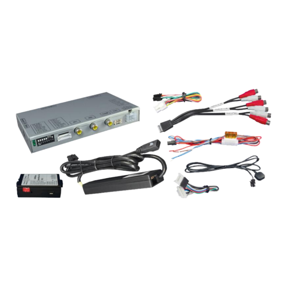
Technical knowledge is necessary for installation. The place of installation must be free of moisture and away from heat sources. 1.1. Delivery contents Take down the serial number of the interface and store this manual for support purposes: ____________________ Version 17.02.2020 HW 16-(V65) CI-VL2-NG4-HU... -
Page 4: Checking The Compatibility Of Vehicle And Accessories
For sound use the possibly existing factory-audio-AUX-input or a FM-modulator. Factory rear-view camera Automatic switch-back from inserted video to factory rear-view camera only while reverse gear is engaged. To delay the switch- back time, additional electronics is required. Version 17.02.2020 HW 16-(V65) CI-VL2-NG4-HU... -
Page 5: Boxes And Connectors
The video-interface converts the connected after-market sources video signals to an LVDS signal which is the inserted into the factory monitor on certain trigger options. 1.3.2. CAN-bus box The CAN-bus box reads digital signals from the CAN-bus and converts them for the video- interface. Version 17.02.2020 HW 16-(V65) CI-VL2-NG4-HU... -
Page 6: Dip-Switch Settings
If set to OFF, the interface switches to factory LVDS picture while the reverse gear is engaged to display factory rear-view camera or factory optical park system picture. If set to ON, the interface witches to its rear-view camera input CAM while the reverse gear is engaged. Version 17.02.2020 HW 16-(V65) CI-VL2-NG4-HU... -
Page 7: Monitor Selection (Dip 7-8)
If power source is not taken directly from the battery, the connection has to be checked for being start-up proven and permanent. 2.1. Place of installation The interface is installed at the rear of head-unit. Version 17.02.2020 HW 16-(V65) CI-VL2-NG4-HU... -
Page 8: Connection Schema
2.2. Connection schema Version 17.02.2020 HW 16-(V65) CI-VL2-NG4-HU... -
Page 9: Connecting Video-Interface And Can-Box For Citroen And Peugeot Vehicles
● Green Ground ● White CAN HIGH ● Grey CAN LOW No liability for vehicle wire colors and pin definition! Possible changes by the vehicle manufacturer. The given information must be verified by the installer. Version 17.02.2020 HW 16-(V65) CI-VL2-NG4-HU... -
Page 10: Connecting Video-Interface For Alfa Giulietta, Citroen And Peugeot Vehicles
Connect white female 6pin Molex connector of the 6pin to 8pin cable to the male 6pin Molex connector of the video-interface. Cut the cables of the 6pin to 8pin cable at the black 8pin connector and connect them as shown in the diagram above. Version 17.02.2020 HW 16-(V65) CI-VL2-NG4-HU... -
Page 11: Connection To The Head-Unit
Remove female 10pin HSD LVDS connector from the rear of the head-unit and connect it to the LVDS-switch-box of the 10pin HSD LVDS cable. Connect female 10pin connector of the 10pin HSD LVDS cable to the male 10pin HSD LVDS connector of the head-unit. Version 17.02.2020 HW 16-(V65) CI-VL2-NG4-HU... -
Page 12: Connecting Peripheral Devices
Connect female 8pin connector of the RGB cable to the male 8pin connector of the video-interface. The loose grey wires have no function and have to be isolated. Connect male 6pin connector of the RGB cable to the after-Market navigation. Version 17.02.2020 HW 16-(V65) CI-VL2-NG4-HU... -
Page 13: Video-Sources To In1 And In2
Note: If only one AV-source shall be connected, it is possible to connect the video output of the AV-source to the video input AV1 of the video-interface and the audio output of the AV- source directly to the point of audio-insertion (e.g. audio AUX input). Version 17.02.2020 HW 16-(V65) CI-VL2-NG4-HU... - Page 14 RCA port AV-Out of the audio cable. Connect the audio-RCA of the AV-source 1 to the female RCA port AV1 of the audio cable. Connect the audio-RCA of the AV-source 2 to the female RCA port AV2 of the audio cable. Version 17.02.2020 HW 16-(V65) CI-VL2-NG4-HU...
-
Page 15: After-Market Rear-View Camera
CAM while reverse gear is engaged. Additionally, the +12V (max. 500mA) power supply for the rear-view camera can be taken from the green wire of the 6pin to 8pin cable. Version 17.02.2020 HW 16-(V65) CI-VL2-NG4-HU... -
Page 16: Case 2: Can-Box Does Not Detect Reverse Gear
Connect reverse gear light signal/power to coil (85) and ground to coil (86) of relais. Connect rear-view camera power and green wire (video interface side) of 6pin to 8pin cable to output (87) of relay. Connect permanent battery power to input (30) of relay. Version 17.02.2020 HW 16-(V65) CI-VL2-NG4-HU... -
Page 17: Video Signal Connection
CAM. Note: Picture settings for CAM input must be done in AV2. 2.7. Connecting video-interface and keypad Connect the female 4pin connector of the keypad to the male 4pin connector of the video-interface. Version 17.02.2020 HW 16-(V65) CI-VL2-NG4-HU... -
Page 18: Picture Settings
Note: The OSD menu is only shown when a working video source is connected to the selected video-input of the interface. The following settings are available: Brightness Contrast Saturation Position H (horizontal) Position V (vertical) Version 17.02.2020 HW 16-(V65) CI-VL2-NG4-HU... -
Page 19: Interface Operation
0.7V with 75 Ohm impedance Temperature range -40°C to +85°C Dimensions video-box 154 x 22 x 92 mm (W x H x D) Dimensions CAN-box 73 x 22 x 45 mm (W x H x D) Version 17.02.2020 HW 16-(V65) CI-VL2-NG4-HU... - Page 20 Camera input picture fluorescent light which shines Test camera under natural light outside the garage. flickers. directly into the camera. Camera input picture is Protection sticker not Remove protection sticker from lens. bluish. removed from camera lens. Version 17.02.2020 HW 16-(V65) CI-VL2-NG4-HU...
- Page 21 Cut the grey wire of 6pin to 8pin and isolate both Interface switches compatibility to vehicle is ends. If problem still occurs, additionally cut the white video-sources by itself. limited. wire of 6pin to 8pin cable and isolate both ends. 10R-03 5384 Made in China Version 17.02.2020 HW 16-(V65) CI-VL2-NG4-HU...
Need help?
Do you have a question about the CI-VL2-NG4-HU and is the answer not in the manual?
Questions and answers