Table of Contents
Advertisement
Quick Links
UM10699
User manual for SPI-bus RTC demoboard OM11059
Rev. 1 — 04 April 2013
Document information
Info
Content
PCF86063BTL, OM11059, demoboard, how to get started, SPI-bus,
Keywords
RTC, Real-Time Clock, tuning
User manual for the RTC SPI-bus demoboard OM11059 which contains
Abstract
PCF85063BTL
User manual
Advertisement
Table of Contents

Subscribe to Our Youtube Channel
Related Manuals for NXP Semiconductors OM11059


Summary of Contents for NXP Semiconductors OM11059
- Page 1 User manual for SPI-bus RTC demoboard OM11059 Rev. 1 — 04 April 2013 User manual Document information Info Content PCF86063BTL, OM11059, demoboard, how to get started, SPI-bus, Keywords RTC, Real-Time Clock, tuning User manual for the RTC SPI-bus demoboard OM11059 which contains Abstract PCF85063BTL...
- Page 2 UM10699 NXP Semiconductors User manual for SPI-bus RTC demoboard OM11059 Revision history Date Description 20130404 new user manual, first revision Contact information For more information, please visit: http://www.nxp.com For sales office addresses, please send an email to: salesaddresses@nxp.com UM10699 All information provided in this document is subject to legal disclaimers.
-
Page 3: Fig 1. Block Diagram Of The Pcf85063Btl Rtc
The PCF85063x are a family of CMOS Real-Time Clocks (RTC) and calendar optimized for low power consumption. Different features sets are available. The OM11059 is the ideal evaluation/demo board to use in the design phase of any project, just power and SPI-bus must be hooked up. -
Page 4: Fig 2. Interfacing To Microcontroller
UM10699 NXP Semiconductors User manual for SPI-bus RTC demoboard OM11059 3. Hardware set-up 3.1 General requirements for the RTC PCF85063BTL The RTC circuit just requires one external part: tuning fork quartz as resonator. The oscillation capacitors are integrated and therefore there is no need for external capacitors. -
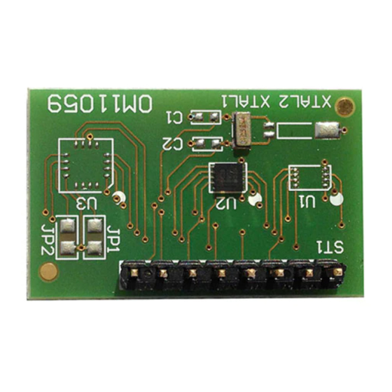
Page 5: Fig 3. Picture And Layout Of Demo Bard Om11059
Fig 3. Picture and layout of demo bard OM11059 The OM11059 allows to easily demonstrating operation of the PCF85063BTL with SPI- bus interface. No need to solder the tiny package to a breadboard 100 mil connector for straight forward connections. -
Page 6: Fig 5. Om11059 Schematics
UM10699 NXP Semiconductors User manual for SPI-bus RTC demoboard OM11059 Fig 5. OM11059 schematics 4. Software set-up 4.1 Functionality The RTC PCF85063BTL is controlled via standard SPI-bus interface. Common SPI protocol applies. Theoretically there is no lower speed limit, however the access of the RTC should be performed within less than 1 second, otherwise time counter increments could be lost. -
Page 7: Software Instructions For Setting The Clock
UM10699 NXP Semiconductors User manual for SPI-bus RTC demoboard OM11059 The RTC PCF85063BTL has a frequency tuning facility; its operation is explained in section 5. The RTC can stay switched on all the time. There is no need to restart or reset the clock. -
Page 8: Rtc Tuning
UM10699 NXP Semiconductors User manual for SPI-bus RTC demoboard OM11059 5. RTC tuning 5.1 Frequency tuning The 32 kHz quartzes are typically sold with a tolerance at room temperature of either ±10 ppm or ±20 ppm. 11.5 ppm corresponds to 1 s/day. -
Page 9: Fig 6. Temperature Averaged Over Application Range 5 °C To 45 °C
UM10699 NXP Semiconductors User manual for SPI-bus RTC demoboard OM11059 (1) Characteristic if tuned to 32.768 kHz at 25 ºC. (2) Characteristic if tuned with the positive offset Δf Fig 6. Temperature averaged over application range 5 °C to 45 °C UM10699 All information provided in this document is subject to legal disclaimers. -
Page 10: Legal Information
Evaluation products — This product is provided on an “as is” and “with all faults” basis for evaluation purposes only. NXP Semiconductors, its affiliates In no event shall NXP Semiconductors be liable for any indirect, incidental, and their suppliers expressly disclaim all warranties, whether express,... -
Page 11: Table Of Contents
Fig 1. Block diagram of the PCF85063BTL RTC ..3 Fig 2. Interfacing to microcontroller ......4 Fig 3. Picture and layout of demo bard OM11059..5 Fig 4. OM11059 block diagram ........5 Fig 5. OM11059 schematics ........6 Fig 6. -
Page 12: Contents
UM10699 NXP Semiconductors User manual for SPI-bus RTC demoboard OM11059 8. Contents Introduction ............3 Key features ............3 PCF85063BTL ........... 3 Hardware set-up ..........4 General requirements for the RTC PCF85063BTL ........... 4 Demo board OM11059A ........5 Software set-up ........... 6 Functionality ............ - Page 13 Mouser Electronics Authorized Distributor Click to View Pricing, Inventory, Delivery & Lifecycle Information: OM11059,598 OM11059UL...
Need help?
Do you have a question about the OM11059 and is the answer not in the manual?
Questions and answers