Table of Contents
Advertisement
Quick Links
UM10817
OM13503, PCA8539 demo board
Rev. 1 — 3 September 2014
Document information
Info
Content
LCD driver, dot-matrix driver, COG, Chip-On-Glass, PCA8539,
Keywords
LPCXpresso, Vertical Alignment, VA
The OM13503 is an LCD demo board which can be used to demonstrate
Abstract
and evaluate the PCA8539 dot-matrix driver. This is a Chip-On-Glass
LCD driver which can drive a dot matrix up to 100 × 18 dots with a display
size of up to 7".
The board is controlled by an LPCXpresso micro controller board, which
contains the LPC1115, a Cortex M0 controller. A free IDE can be
downloaded in order to modify the software.
Supply of the board can be done via an AC adapter or USB connector.
User manual
Advertisement
Table of Contents

Subscribe to Our Youtube Channel
Related Manuals for NXP Semiconductors UM10817


Summary of Contents for NXP Semiconductors UM10817
- Page 1 UM10817 OM13503, PCA8539 demo board Rev. 1 — 3 September 2014 User manual Document information Info Content LCD driver, dot-matrix driver, COG, Chip-On-Glass, PCA8539, Keywords LPCXpresso, Vertical Alignment, VA The OM13503 is an LCD demo board which can be used to demonstrate Abstract and evaluate the PCA8539 dot-matrix driver.
- Page 2 UM10817 NXP Semiconductors OM13503, PCA8539 demo board Revision history Date Description 20140903 Initial version Contact information For more information, please visit: http://www.nxp.com For sales office addresses, please send an email to: salesaddresses@nxp.com UM10817 All information provided in this document is subject to legal disclaimers.
-
Page 3: Contents
UM10817 NXP Semiconductors OM13503, PCA8539 demo board 1. Introduction This user manual describes the OM13503 demo board. The board consists of a base board, with a plugged in LPCXpresso board containing the microcontroller to control the display driver. The PCA8539 is a peripheral LCD driver which generates the drive signals for a dot matrix display of up to 18 rows and up to 100 columns. -
Page 4: Board Description And Layout
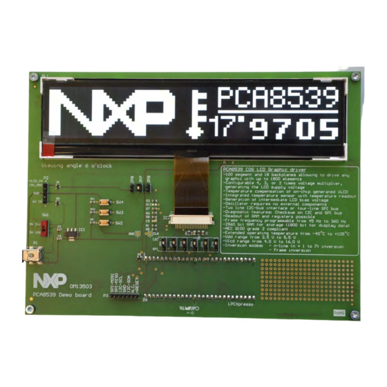
UM10817 NXP Semiconductors OM13503, PCA8539 demo board 2. Board description and layout Fig 1 the top view of the board is given. Fig 1. Top view of OM13503 demo board For best optical performance, remove the protective foil from the display. A red colored pull tape can be found on the bottom left of the display. -
Page 5: Power Supply
UM10817 NXP Semiconductors OM13503, PCA8539 demo board 2.1 Power Supply Please refer to the schematic diagram of the board, which is given in 1. Via mini-USB connector P1. Now the 5 V come directly from the USB port. This supply is used for the PCA8539 directly, as well as to supply a 3.3 V regulator. The output of the regulator is used for the back light and to supply the micro controller. -
Page 6: Jumpers
UM10817 NXP Semiconductors OM13503, PCA8539 demo board 2.3 Jumpers The board contains a number of jumpers. Below they are listed, along with their functionality. • JP1 through JP6: They are all used to select either the I²C-bus interface, or the SPI interface. -
Page 7: Board Schematic And Layout Of Om13503
UM10817 NXP Semiconductors OM13503, PCA8539 demo board expansion boards to provide a greater variety of interfaces, and I/O devices. The on- board LPC-Link debugger provides a high-speed USB to JTAG/SWD interface to the IDE and it can be connected to other debug targets such as a customer prototype. Users can also use the LPCXpresso IDE with the Red Probe JTAG adapter from Code Red Technologies. - Page 8 Fig 3. Schematic of OM13503...
-
Page 9: Display Module
UM10817 NXP Semiconductors OM13503, PCA8539 demo board 4. Display module The display is a Passive Matrix Vertically Aligned (PMVA) negative display providing a very dark background with a very wide and symmetric viewing angle. 5. Software code example The PCA8539 data sheet contains all the commands and their description. In order to write software for this driver, it is necessary to read the datasheet. -
Page 10: References
UM10817 NXP Semiconductors OM13503, PCA8539 demo board 6. References The documents listed below provide further useful information. They are available at NXP’s website www.nxp.com. LPCXPresso: Getting started with NXP LPCXpresso PCA8539: Product data sheet UM10204: I²C-bus specification and user manual AN11267: EMC &... -
Page 11: Legal Information
NXP Semiconductors, its affiliates and their suppliers expressly disclaim all warranties, whether express, In no event shall NXP Semiconductors be liable for any indirect, incidental, implied or statutory, including but not limited to the implied warranties of non- punitive, special or consequential damages (including - without limitation - infringement, merchantability and fitness for a particular purpose. -
Page 12: List Of Figures
UM10817 NXP Semiconductors OM13503, PCA8539 demo board 8. List of figures Fig 1. Top view of OM13503 demo board ....4 Fig 2. PCB layout of OM13503 ........7 Fig 3. Schematic of OM13503 ........8 UM10817 All information provided in this document is subject to legal disclaimers. -
Page 13: Table Of Contents
'Legal information'. © NXP B.V. 2014. All rights reserved. For more information, please visit: http://www.nxp.com For sales office addresses, please send an email to: salesaddresses@nxp.com Date of release: 3 September 2014 Document identifier: UM10817... - Page 14 Mouser Electronics Authorized Distributor Click to View Pricing, Inventory, Delivery & Lifecycle Information: OM13503UL...
Need help?
Do you have a question about the UM10817 and is the answer not in the manual?
Questions and answers