Table of Contents
Advertisement
Quick Links
Advertisement
Table of Contents

Related Manuals for NXP Semiconductors OM40006


Summary of Contents for NXP Semiconductors OM40006
- Page 1 UM11079 IoT Module Base Board User Manual Rev. 1.0 — March 20, 2018 User manual Document information Info Content Keywords LPC54018, LPC54018 IoT Module Baseboard, Baseboard OM40006, OM40007 Abstract IoT Module Baseboard User Manual Arrow.com. Downloaded from...
- Page 2 UM11079 NXP Semiconductors IoT Module base board Revision history Date Description <20171116> OM40006 User Manual release Contact information For more information, please visit: http://www.nxp.com For sales office addresses, please send an email to: salesaddresses@nxp.com UM11079_OM40006.docm All information provided in this document is subject to legal disclaimers.
-
Page 3: Fig 1. Iot Module Baseboard Underside View (No Module Fitted)
IoT Module base board 1. Introduction The OM40006 IoT Module Baseboard is designed to provide access to the broad range of peripherals available on NXP WiFi-enabled IoT modules, such as the LPC54018 IoT Module (OM40007). The board includes a debug probe based on the LPC-Link2 design used in many of NXP’s range of LPCXpresso boards, and in the standalone debug LPC-... -
Page 4: Feature Summary
NXP Semiconductors IoT Module base board 2. Feature summary The OM40006 board includes support for the following features (availability of these features depends on the capabilities of the installed IoT Module): • On-board, high-speed USB based, Link2 debug probe with CMSIS-DAP and... -
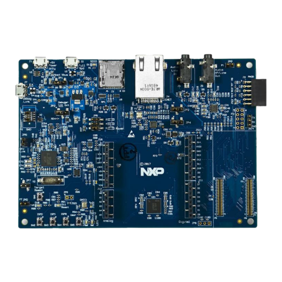
Page 5: Fig 2. Om40006 Main Feature Layout
(1) Red is used to highlight key components, brown for buttons and LEDs, green for connectors and blue for expansion connectors. Fig 2. OM40006 main feature layout The LCD panel is mounted on the reverse side of the board, connected to the circuitry via two flex cable connectors. It should not normally be necessary to remove the LCD or access these connectors;... -
Page 6: Fig 3. Jumper And Led Locations
UM11079 NXP Semiconductors IoT Module base board Fig 3. Jumper and LED locations The function of each jumper is listed in Table 1. Table 1. Jumpers Circuit ref Description Ref section USB0 Vbus select schematic When using USB0 as a device interface, place in position 1-2... - Page 7 Link2 internal flash with a new image (using the LPCScrypt utility) or to use the MCUXpresso IDE with CMSIS-DAP protocol. Note that the OM40006 Link2 flash is pre-programmed with a version of CMSIS-DAP firmware by default. UART Bridge / P4 Header selector.
- Page 8 UM11079 NXP Semiconductors IoT Module base board Table 2. LEDs, buttons and connectors Circuit Ref Description Ref section SD card slot power enable This LED illuminates when power is enabled to the SD card slot (controlled by Module P5 pin 83 (port P2-5)) Link2 boot mode Link2 LPC43xx BOOT0_LED indicator.
-
Page 9: Getting Started
UM11079 NXP Semiconductors IoT Module base board Circuit Ref Description Ref section Module Full Speed USB connector (USB0) 6.2.2 This micro AB connector enables connection from the Module USB0 port to host or slave devices. An adaptor (not supplied) is typically required to connect USB slave devices (mouse, keyboard, etc.) -
Page 10: Installing An Iot Module
USB cable to connector J7 (“Debug-Link”). The Module installed will boot and run any pre-installed software (refer to the manual for the module being used.) 5. Allow about 10 seconds for the OM40006 devices to enumerate for the first time; the device will appear as “LPC Device”. UM11079_OM40006.docm All information provided in this document is subject to legal disclaimers. -
Page 11: Rd Party Tools (E.g. Keil And Iar)
4. Connect the OM40006 board to the USB port of your host computer, connecting a micro USB cable to connector J7 (“Debug-Link”). 5. Allow about 10 seconds for the OM40006 devices to enumerate for the first time. It is not necessary to check the Hardware Manager, however if this is done there will be five devices;... -
Page 12: Starting A Debug Session Using An External Debug Probe
VCOM port can be used if the board is running an application when no debugger is running. In order to correctly install and use the Link2 device on the OM40006 (as will be required for any debugging) for host computers running Window 7 or 8, drivers must first be installed. -
Page 13: Fig 4. Identifying The Vcom Port
UM11079 NXP Semiconductors IoT Module base board the IDE boots the debug probe. The debug probe is booted once a debug session is started (i.e. the IDE attempts to download code to the target). 4.1 What the Link2 boot LED indicates LED D8 is the Link2 MCU BOOT0_LED indicator. -
Page 14: Board Power Connections & Measurement
MCUXpresso IDE) as described earlier in this section. 5. Board power connections & measurement The OM40006 board requires +5V input to power the on-board voltage regulators which in turn power the Link2 debug probe and other +3.3V circuits, the installed module and and the Arduino +5V and +3.3V power rails. -
Page 15: Usb Full Speed Port (Usb0)
UM11079 NXP Semiconductors IoT Module base board Function TXD (from Module) 6.2 USB Full Speed port (USB0) The Full Speed (FS) USB port from the installed Module is connected to micro AB USB connector J2. This section describes functionality support by this port and associated jumper settings. -
Page 16: Arduino Uno Expansion Connectors
C interface signals. 6.5 Arduino UNO expansion connectors The OM40006 board includes four expansion connectors (J9-J12) compatible with Arduino UNO revision 3. These connectors provide access to I C, USART, SPI and several GPIO/INT/PWM connections. Note that several of the signals available at these connectors are shared with other connectors or board functions, so might not be usable if those other functions are being used by other devices. -
Page 17: Ethernet Port
J12 pin 6 User push button 6.6 Ethernet port The OM40006 board includes an on-board LAN8720A-CP PHY and RJ45 jack with integrated link status LEDs. The MCUXpresso SDK package for each NXP Module includes drivers for use of this Ethernet PHY. -
Page 18: Fig 5. Line Input Circuitry
Module used.) 8.3 SD card The micro SD card (J3) includes in the OM40006 board provides a 4-bit SDIO interface to support memory cards and other compatible modules. Power enable to the socket is provided via P5 pin 83 (PIO2-5), with LED D1 providing a visual indication when power is applied. -
Page 19: Digital Microphone
UM11079 NXP Semiconductors IoT Module base board 8.5 Digital Microphone A low power Knowles SPH0641LM4H digital microphone is incorporated on the board, for use with Modules that support direct interfacing to this type of PDM microphone. Note that the Knowles digital microphone is designed to be mounted on the underside of a board, with audio passing through a hole in the board. -
Page 20: Legal Information
Semiconductors products in order to avoid a default of the applications and In no event shall NXP Semiconductors be liable for any indirect, incidental, the products or of the application or use by customer’s third party punitive, special or consequential damages (including - without limitation - customer(s). -
Page 21: Table Of Contents
10. List of figures Fig 1. IoT Module Baseboard underside view (no module fitted) ............ 3 Fig 2. OM40006 main feature layout ......5 Fig 3. Jumper and LED locations ........ 6 Fig 4. Identifying the VCOM port ....... 13 Fig 5. -
Page 22: List Of Tables
UM11079 NXP Semiconductors IoT Module base board 11. List of tables Table 1. Jumpers ............6 Table 2. LEDs, buttons and connectors ......8 Table 3. P4 connections ..........14 Table 4. Host Expansion Header signals ...... 15 Table 5. -
Page 23: Contents
UM11079 NXP Semiconductors IoT Module base board 12. Contents LCD with capacitive touch ........ 17 Introduction ............3 Audio codec ............17 Feature summary ..........4 SD card ............18 Board layout and settings ........4 Accelerometer ..........18 Getting Started ............ 9 Digital Microphone ..........
Need help?
Do you have a question about the OM40006 and is the answer not in the manual?
Questions and answers