
Subscribe to Our Youtube Channel
Related Manuals for NXP Semiconductors NTAG 5 Series


Summary of Contents for NXP Semiconductors NTAG 5 Series
- Page 1 Quick Start Guide Part Number Here OM2NTA5KIT Exploring the exclusive features of NTAG 5 switch, NTAG 5 link and NTAG 5 boost NTAG 5 FAMILY - DEMOBOARDS Arrow.com. Downloaded from...
- Page 2 Quick Start Guide GET TO KNOW THE NTAG 5 switch board Button to show general Antenna purpose 54x24 mm input LED to show general purpose output and pulse width NTAG 5 switch modulation NTP5210 Front side of NTAG 5 switch demo board Arrow.com.
- Page 3 Quick Start Guide GET TO KNOW THE NTAG 5 link board I²C 6-axis sensor to show I²C master feature I²C FRAM to show easy memory Antenna extension 54x24 mm LEDs to show regulated energy harvesting NTAG 5 link NTP5332 Front side of NTAG 5 link demo board Arrow.com.
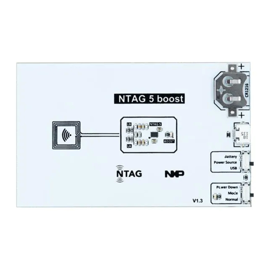
- Page 4 Quick Start Guide GET TO KNOW THE NTAG 5 boost board Battery supply supply Antenna 10x10 mm Select Battery or USB supply Use hard power down to save energy LED to NTAG 5 boost show NTA5332 If LED is received on, board command is ready to...
- Page 5 www.nxp.com When no board is connected, status switches to “polling” NTAG 5 show card tab Arrow.com. Arrow.com. Arrow.com. Arrow.com. Arrow.com. Downloaded from Downloaded from Downloaded from Downloaded from Downloaded from...
- Page 6 www.nxp.com Use side menu to navigate NTAG 5 demo navigation Arrow.com. Arrow.com. Arrow.com. Arrow.com. Arrow.com. Arrow.com. Downloaded from Downloaded from Downloaded from Downloaded from Downloaded from Downloaded from...
- Page 7 www.nxp.com When button is pressed, bulb goes on When board is connected, Explore GPO status and PWM switches to “activated” NTAG 5 switch general purpose input Arrow.com. Arrow.com. Arrow.com. Arrow.com. Arrow.com. Arrow.com. Arrow.com. Downloaded from Downloaded from Downloaded from Downloaded from Downloaded from Downloaded from Downloaded from...
- Page 8 www.nxp.com Chang settings of LED brightness When board is connected, Explore GPIO status or change switches to loop speed “activated” NTAG 5 switch general purpose output and pulse width modulation Arrow.com. Arrow.com. Arrow.com. Arrow.com. Arrow.com. Arrow.com. Arrow.com. Arrow.com. Downloaded from Downloaded from Downloaded from Downloaded from...
- Page 9 www.nxp.com Configure how fast brightness changes Explore GPIO and PWM features NTAG 5 switch settings Arrow.com. Arrow.com. Arrow.com. Arrow.com. Arrow.com. Arrow.com. Arrow.com. Arrow.com. Arrow.com. Downloaded from Downloaded from Downloaded from Downloaded from Downloaded from Downloaded from Downloaded from Downloaded from Downloaded from...
- Page 10 www.nxp.com X and Y orientation of 6 axis sensor When board is connected, Explore memory status extension or switches to configure output “activated” voltage NTAG 5 link read sensor Arrow.com. Arrow.com. Arrow.com. Arrow.com. Arrow.com. Arrow.com. Arrow.com. Arrow.com. Arrow.com. Arrow.com. Downloaded from Downloaded from Downloaded from Downloaded from...
- Page 11 www.nxp.com Write NXP Image read logo or from FRAM photo from will be camera to displayed FRAM When board is connected, Explore status sensor tag or switches to configure “activated” output voltage NTAG 5 link extend user memory Arrow.com. Arrow.com. Arrow.com.
- Page 12 www.nxp.com Change output Image read voltage. from FRAM You need to re- will be connect the displayed board afterwards to make settings When board is connected, Explore status sensor tag or switches to memory “activated” extension NTAG 5 link set output voltage Arrow.com.
-
Page 13: Install App
Quick Start Guide NTAG 5 switch On top NTAG 5 boost FEATURES FEATURE ISO/IEC 15693 compliant Active Load Modulation • • NFC Forum Type 5 Tag • compliant STEP-BY-STEP General Purpose Input and • INSTRUCTIONS Output (GPIO) Pulse Width Modulation (PWM) •... - Page 14 www.nxp.com STEP-BY-STEP INSTRUCTIONS (cont.) Explore NTAG 5 switch Explore read range of demo board boards Make sure status is “activated” Status changes from “polling” to “activated” as soon board is detected Press button on board to explore GPIO functionality Select ON/PWM/OFF to explore GPIO and PWM functionality Change brightness of LED in a loop Explore NTAG 5 link...
-
Page 15: Warranty
SUPPORT Get Started Visit www.nxp.com/support for a list of phonenumbers within your region. Download installation software and documentation WARRANTY “Jump Start Your Design” Visit www.nxp.com/warranty for complete nxp.com/demoboard/OM2NTx5332 warranty information. www.nxp.com NXP and the NXP logo are trademarks of NXP B.V. All other product or service names are the property of their respective owners.
Need help?
Do you have a question about the NTAG 5 Series and is the answer not in the manual?
Questions and answers